Make sense please

That's true, I've seen connectors used with dead pins on them that don't connect to anything. Like a 10 pin Julet connector with only 9 pins live.

Even worse, I've received some stuff that had extra wires at the end that didn't go to a pin. Like a 10 pin Julet connector with 11 wires going to the end and instructions to cut the connector if you need the eleventh. I really hate that.

Sometimes the dead pin is justified because it stops someone from plugging a connector in backwards and shorting something. The extra wire business is never justified IMO.
 
Perhaps you can take some pictures and post them here so we can talk about what you have?
Or if you know of a page online showing that exact item (perhaps where you bought it from) you can post that for us to see.
 
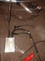
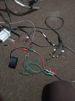
Well, here's a couple pictures no, how it's gonna help you. I don't know if how's gonna help you. I'll try to explain what you're looking at. But I can't find the Ignition wire problem. Can't see any of the wiring
So you got your basic motorline, then you get the 1to4?9pin, A three pin pedal assist line, a two pin line
The 1T0 4 splits up and To your throttle line brakes display that you probably already know. So if I'm trying to wire up this new throttle, I'm supposed to runner line from the yellow to the Battery,and blue To the on offswitch with I guess another line coming to the switch from the battery We're yellow line.
No, I'm confused again. Is it 5 pen throttled Sorry I'm so stupid, isn't it? All makes sense at some point i've done it before, But not with jolette connectors . How do I find the Ignition cable? It also this learning wire. And I can't seem to find any information you know I put in specific controller numbers all that stuff I can't get any information on the fruit controy i'm done if you're just gonna hang out
 

Attachments

  • 1703308935745652775386800607259.jpg
    1703308935745652775386800607259.jpg
    2.6 MB · Views: 20
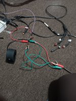
All I have done is hardwired. The9wires Coming out of the control box. To the 4 in hopes that The Throttle line and the display which I'm not even using Since my photo has a power on switch, I'm hoping that will turn it on, but it doesn't seem to be working cause she's can't find the Ignition wire and it's what I've done. Yellow and blue are clipped together and ran to the power From battery, so can't find a dishwasher. Not working
 
Here's the picture that didn't go through
 

Attachments

  • 1703378279932973041322653395966.jpg
    1703378279932973041322653395966.jpg
    2.7 MB · Views: 12
  • 17033784690013775504883167544350.jpg
    17033784690013775504883167544350.jpg
    2.3 MB · Views: 12
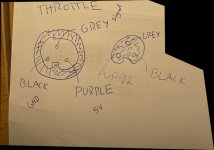
A throttle requires three wires: +5V, GND, and signal. If you have a throttle, it has those three wires. Some throttle units also feature a state of charge indicator (in which case they need a battery+ wire) and/or an enable "on/off" switch. If those are the functions your display has, then that's what the wires are for.

Usually but not always, +5V is red and GND is black. Throttle signal is often green or white, but there are lots of exceptions.

You can work a lot of this out using a multimeter. Set it for DC voltage, check red and black to see if you get 5V. If yes, then stay on black and check the other wires for battery voltage. When you find that, any remaining wires that show 0V relative to GND are signals to the controller: throttle, enable, whatever according to the display's functions.
Yeah, I get that you're trying to figure out why is that the control box sends a red wire to the controller. I mean, that is looped with the initial wire, I believe of full battery voltage. Where's the 5 V come at it's sending 50 V to the freaking g****** frado. How is the Friday with the 5 V anyway, I don't get it. I'm just gonna f****** throw it all in the free world tracks, f*** it all nobody can help me. It's things was working fine. I told all I do was trying to replace a g****** f****** throttle and I can't do it. Every f****** Friday I just ordered a new swallow. When they don't need to work, I'm praying. F****** throttle orange, I don't even know where to weaken and it doesn't work. I'm sick of this shit don't just before
 
I hope I'll figure out how to actually get this done. And then post it should be so confusing on almost computer stuff. I know I'm stupid but really I ask simple questions and they're so simple. Nobody thinks I'm serious but someone. Please explain to me if you cand if I have a throttle with display in one unit. It has 5 or 6 wires. There's no separate throttle line for that, but it's not separate. It comes with the 5 or 6 pin thing. It's all one unit, so why is everyone telling me? There's a separate throttle line when there's not. So now I'm trying to attach a regular 3 wired throttle to the system. So i'm guessing that the throttle wires are in the five or six pen connector which is
Yeah, it's not rare to have a throttle combined with a voltage readout and/or ignition switch, which add more wires:

I wouldn't call it a display, that would confuse people. Displays often take a signal wire that uses a protocol to communicate a set of data displayed on the display like speed and trip distance. A throttle with a voltage readout doesn't.
 
Ok, I'm trying to be calm about this really upset, so I've been trying to do is replace a throttle. Apparently at all 4 of the troubles I had were no good, so I ordered a new one I actually dialed or 2 new ones 1 I f***** u* and the other 1. Apparently doesn't work. So how am I looking anything fixed? I keep saying I got faulty parts first oftalk. But, once I was doing something according to my tester. Brand new swallows not doing anything according to my tester. I got a purple and red wire loop together. I think it's a unique mission wire. I don't know nobody will tell me. You didn't even get any that t**, you. You know i'm not proof reading this
 
Ok, I'm trying to be calm about this really upset, so I've been trying to do is replace a throttle. Apparently at all 4 of the troubles I had were no good, so I ordered a new one I actually dialed or 2 new ones 1 I f***** u* and the other 1. Apparently doesn't work. So how am I looking anything fixed? I keep saying I got faulty parts first oftalk. But, once I was doing something according to my tester. Brand new swallows not doing anything according to my tester. I got a purple and red wire loop together. I think it's a unique mission wire. I don't know nobody will tell me. You didn't even get any that t**, you. You know i'm not Proof reading right now, I'm losing my mind. Why is there a purple and red wire loop together, shouldn't it be a smaller red wire to use the throttle or up the display or whatever works fine when there's a display with a frottal? But when there's not one, it doesn't wasting too much. Wasting too much money on this s***Got a control box with joel and connectors I can all frock it
 
I'm giving up frock at all i'm just gonna take the bus everywhere and in F*** the world and everything in it? That's how I feel about gets out of your talking, I feel now I'm taking all this s*** and throw it out the street f*** it. I just take the bus and walk and hunch over every 20 feet because I need spinal surgery and I can't be walking but nobody wants to f****** give me straight answers. Don't even make anything so complicated. Nobody can tell me why there's a red wire and a purple wire loop together with the and sending 50 V to the throttle. When you're supposed to be 5 vols being Gotham access. Not to make sense anymore. I give up even though I've done it several times before. I'm giving up even though I've done it before. Can you breathe that s***Do I become a electrician? You guys can't have any bike.
Where's the part where I frocking post the shit where's the parkway I postedsktd
 
Could you perhaps send us the website where you bought what you have on the bicycle - the controller, LCD, and so on?

I had, in fact, two LCDs with built-in throttle, one with five wires and the other with six wires. The display with five wires communicates all information to the controller via UART, such as how much the person presses the throttle. The one with six wires is an analog signal that goes to the controller, for example, a controller with a three-pole throttle connector with a signal input.

In this case, forget about 0V and 5V because the throttle contact (0V and 5V) is established through the LCD.

I apologize in advance if I haven't fully understood the issue you're experiencing.

IMG_3980.JPG
 
Last edited:
> Nobody can tell me why there's a red wire and a purple wire loop together with the and sending 50 V to the throttle. When you're supposed to be 5 vols

Ignition is pretty much always full battery voltage. That's a common question:

If there's a +5V somewhere, it's generally to power the hall effect sensor in the throttle and provided by the controller after going through a DC converter. Not involved in the ignition switch which is just the ignition wire getting switched to battery positive. Throttle is typically +5V, ground, and a signal wire that changes voltage as you twist it. Easy to distinguish the throttle wires from each other with a voltmeter.
 
Last edited:
Could you perhaps send us the website where you bought what you have on the bicycle - the controller, LCD, and so on?

I had, in fact, two LCDs with built-in throttle, one with five wires and the other with six wires. The display with five wires communicates all information to the controller via UART, such as how much the person presses the throttle. The one with six wires is an analog signal that goes to the controller, for example, a controller with a three-pole throttle connector with a signal input.

In this case, forget about 0V and 5V because the throttle contact (0V and 5V) is established through the LCD.

I apologize in advance if I haven't fully understood the issue you're experiencing.

View attachment 344886
Well, that would explain it I had to do that somehow when I was going over everything in my head outloudly. And what not? I'm sure you're gonna have to be something in the l. C. D. That reduce is the voltage to the throttle D*** if I wasn't right. Thanks for Confirming that I guess great minds think alike. LOLI laughed. Because I'm stupid when it comes to all But I guess I'm starteing to get it ,before I read your Post. That's what I was guessing. But I fixed the whole problem I. ordered another control box comes with a It's a Compatible combination display/throttle that's right, that's what I did and I solved the problem. But Really, I'm glad you confirmed That Suspicion of mine happy holidays and what not gonna be hunting for me next week. More than likely when I can't find the ignition wire again
 
When I ordered that control box it came with a problem display combo makes sense. Now no, that's a different one I don't know what I'm talking about, but it's okay to hold jolette's connections thing that there's a nightmare huh? I'm sorry we're just trying to use that right. No control box, can you use it? There's an idea if somebody can give me a contact information for this k cheap company. The mysterious KT makers so diagrams are trumpets for these people.
Because when I ordered the one with the Joel. That connectors, it was supposed to be the exact same boxes. That
That was awesome.1e1eeseesdlhgssettkeee
 
Yeah, there's no standard for what the individual pins of a Julet connector are for. You have to check the specs for the two parts on either side of the connection, and sometimes chop it off and rewire. And not every controller is compatible with every display/throttle even after that.
 
I'd open up your old controller and measure where each wire on the board inside goes to on it's respective connector pin, and write those down for each pin and each wire for reference.

If the wires on your new controller are marked the same on it's board inside, you can transplant the connectors/cables from the old controller to the new one, replacing the entire new harness with the entire old one, to make things "easy". If they're not marked the same then you'd need more verification before doing this.

But that's where I'd start if I was doing this. taking good clear direct-sunlight-lit pics of everything in every step as I go, and documenting it all, so it could be undone if necessary, or making it easier to troubleshoot later.


FWIW, there are diagrams out there of the common pin connection order for most of these Julet and Higo connectors, some of which can be found in image searches like this:
etc

and on ebikes.ca's connectors page
I have the same problem. I can't get any information on the joilet connectors the brand new control box I can't use. I can figure out easily what colors they are on the inside but I don't know what they're function is . Why can't we get any information on these things? Mine came with diagram diagram for the regular connectors, not the jolette.
 
So while I'm waiting on a new control box with compatible throttle/display controller, that's all gonna work to Be delivered, I'm trying to find out what these 3 wires are on my K2D12torque Sensor that are yellow purple and black 3 wires, it's just a simple thing
 
I'm trying to find out what these 3 wires are on my K2D12torque Sensor that are yellow purple and black 3 wires, it's just a simple thing
You're right, it's a simple thing. But that's not a torque sensor; it's a cadence sensor.

Get your multimeter, set it to DC voltage. Assume black is GND. Power up and enable the controller, figure out which of the other wires shows +5V relative to GND. The other one is the return signal.

The more customary color scheme for PAS wires is yellow, brown, black. If black is in the right pin location, and the plugs are compatible, I'd plug it in and see if it works.
 
I think the communications issue is more generational than locational.

I am gonna hazard a guess that MikeMorrison is fairly young (ok, I am bloody old, so to be more specific, under 23, over 13.) I had this problem fairly often while I was serving. Youngsters appear to create a new language every 4-5 years. I was literally the same age as a lot of the guys serving under me, but grew up in boarding schools and orphanges before that. I had very little in common with my troops.

I literally have nothing to offer the conversation except as an observer. I have never worked with any of this equipment. The adviso I can give other newbs...

Don't buy anything without having a detailed plan. You can cheat by the EE education if you just listen to people that have done it.. Branching out into wild new territory usually leads to confusion and failure.

Best of luck everyone, I have to say, you are a lovely bunch of people. The patience and desire to help speaks very well of all of you...
 
I'll just run away attached some somewhere else, he would have those. I'm gonna pretty good, guess you're so far, but I don't seem to be any way to actually test this thing to figure out what's what. Yes, I wouldn't know what it is. I was
You're right, it's a simple thing. But that's not a torque sensor; it's a cadence sensor.

Get your multimeter, set it to DC voltage. Assume black is GND. Power up and enable the controller, figure out which of the other wires shows +5V relative to GND. The other one is the return signal.

The more customary color scheme for PAS wires is yellow, brown, black. If black is in the right pin location, and the plugs are compatible, I'd plug it in and see if it works.
So I hook up an old display/broken throttle combo thing, so I can get the 5 V to come out of the control box. It works fine until I try to plug in the pedalicious sensor than the voltage changed on me.when I plugged up sensor the Voltage goes down a About 2 V. I'm still not sure which wires are which still. I've tried to bunch of combinations and doesn't seem to work.
Keep working on it, I guess.
 
I think the communications issue is more generational than locational.

I am gonna hazard a guess that MikeMorrison is fairly young (ok, I am bloody old, so to be more specific, under 23, over 13.) I had this problem fairly often while I was serving. Youngsters appear to create a new language every 4-5 years. I was literally the same age as a lot of the guys serving under me, but grew up in boarding schools and orphanges before that. I had very little in common with my troops.

I literally have nothing to offer the conversation except as an observer. I have never worked with any of this equipment. The adviso I can give other newbs...

Don't buy anything without having a detailed plan. You can cheat by the EE education if you just listen to people that have done it.. Branching out into wild new territory usually leads to confusion and failure.

Best of luck everyone, I have to say, you are a lovely bunch of people. The patience and desire to help speaks very well of all of you...
56 smart-ass
 
Back
Top