mounting hall sensors to R/C brushless motors

5 more days and we will all be in business.
I am selling the controllers I have now for cheap
Many people value the soft start program... and for $57 shipped, who can complain?
Geoff has made his offer in the other forum as well.

I have committed to buying a minimum of 10 of the new 18 fet controllers
I will be selling these at or below cost to anyone who wants one.
I have heard details of these new controllers and I think everyone will be pleased
Several bugs are corrected, the chip is better, the shunt is better....

This time next week we are all going to be ridding our bikes at 60MPH :mrgreen:

Cheer up bums!
All of you hard core geeksters know that any project that is easy is not worth doing.
It is the trials and tribulations you go through on the way that make the success so much more fun.

-methods
 
Nice one, Methods!

I've done a quick experiment with the delta to wye conversion this evening and am pleased to say it works extremely well indeed. I've not mounted the hall sensors yet, so I jury rigged the motor up to run with my cheap 120A ESC. The max speed is reduced pretty much exactly as expected and the torque has gone up massively. Whereas I could easily stop the motor when it was just trickling over at it's lowest speed when it was wired delta, just by grabbing the shaft with my fingers, now it's wired wye I cannot make it stall by grabbing the shaft. Not a scientific test, but enough to convince me that this is a pretty good mod.

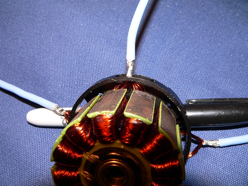
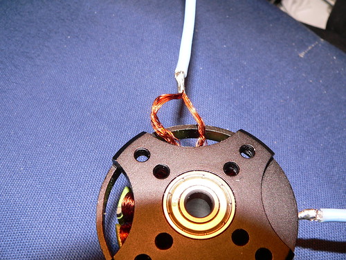
The mod itself is easy. Just push the outer two of the three phase wires back into the motor body, then ease them out of the cooling slots (see picture). Once you have all three wires separated out, twist the wires in the reverse direction to get them to separate out a bit. You may need to ease the wires away from some glue, but I found this came away fairly easily on my motor. Then get a smooth stick (I used a bit of 1/8th hardwood dowel sanded to a rounded point, like a marlin spike) and sort the wires into the two winding terminations that are connected to each phase wire. This is easier if you shine a bright light into the motor to see where the wires come from.

3451165926_b75e916d55.jpg


3450355887_4bc26157c9.jpg


Once the wires are separated out, the same wire in each pair needs to be connected back to the phase wires (i.e take the left wire in each pair and use it as the phase wire, or vice versa, it doesn't matter as long as you're consistent). The other three wires need to be connected together and insulated with a sleeve. With care, the centre join wires can be fed back into the motor, in the space around the base of the stator and the new phase wires can be fed back through the original wire exit slot. Alternatively, you can bring all six wires out and use a delta-wye switch to change the motor from high speed to low speed.


Once I have the Hall sensors fitted to this motor I will try and do a direct comparison of the wye and delta motors using the Infineon controller.

Jeremy
 
Wow. . . This is great.
I have an entire box full of 2g, 5g, and 10g motors that have too high of a KV for the kind of planes I like to build.
Now maybe there is hope to save the motors!

D1000-7700.jpg


Nice thing about testing motors with a prop is that you can put the motor on a scale, measure the thrust and RPM, Voltage and Current.
Make your changes and test again. I guess thats like a dyno of sorts.

Good work!

-methods
 
I finished testing the motor in wye this afternoon, now fitted with Hall sensors and running on the Infineon. As far as I can tell it runs exactly as theory would predict, about 0.57 times the speed and about 1.73 times the torque. Slow speed is very slow indeed, just 84 rpm! At this very low speed the motor has masses of torque, I can't stop it by grabbing the shaft. I want to use this motor to directly drive a small prop for an electric boat, where I'm after good efficiency. I tried building a belt drive reduction, a bit like Matt's system, but found that the losses in driving the belt were too great - the belt drive used about 24 watts with no prop drive. As this boat probably only needs around 50 to 60 watts to propel it through the water at around 4 kts, losing 24 watts in a reduction drive was just too big a penalty to pay.

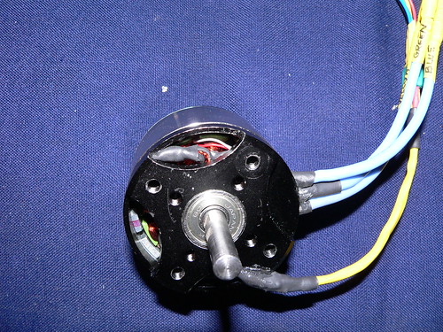
Here's a photo of the finished motor. The yellow cable at the bottom is the hall sensor lead. You can just see the wye centre tap join through the top ventilation hole.

3455445773_e59e0bc945.jpg


Jeremy
 
Very nice Jeremy. Excellent work and documentation, but who cares about boats! :wink: Put that thing on a bike :lol:
 
etard said:
Very nice Jeremy. Excellent work and documentation, but who cares about boats! :wink: Put that thing on a bike :lol:


Actually, I would love to have a small electric drive system for a boat. I use a trolling motor (with a big deep discharge battery) on a canoe and would love to have a lightweight system instead. Maybe we need to start another forum just for boats. :)
 
Well, this forum is about electric vehicles, so my guess is that a boat is a vehicle just as much as a bike.

My goal is to make a solar powered cruising boat, probably an open canoe (I've just bought the plans for the Raven on this site: http://www.selway-fisher.com/Opcan16.htm).

I've looked at the small trolling motors, but they aren't too efficient. They seem to use brushed motors running from either a 12V or 24V battery pack. I reckon that there are useful efficiency gains to be had by upping the voltage of the battery, using a direct drive brushless motor with low bearing drag and generally trying to optimise everything.

I love the idea of being able to cruise under just the power of the sun.

Jeremy
 
I am working on a boat too. :)
I want to be able to leverage our Ebike packs for a trolling type setup.
My wife likes to go out on the water but she will not tolerate ICE motors
(and I wont tolerate paddling / rowing!)

I told her she can paddle and I will operate the electric throttle :mrgreen:

-methods
 
I'm eventually going to do a small boat/dinghy setup as well. What I really want to do, though, is a JetSki conversion. There's a ton of early 2-stroke models that would be perfect for a conversion, as they are a bit smaller, compared to the big 4-stroke models sold these days. They don't sell 2-strokes in California anymore, but I'm guessing there's quite a few used ones out there. :)
 
I don't know whether or not this is of any use, but I've been doing a bit of digging around in to how much power it takes to propel a canoe. It seems that a very fit paddler can generate around 45 watts or so, and sustain this for an hour or two. Burst power may be as high as 70 watts.

Boat propulsions system are simply appallingly inefficient compared to a bike. Cyclists complain about losses of more that around 5% in the drive train, but a prop drive boat will easily lose 50% or so of the input power in it's drive train. There are ways to improve this though. A direct drive prop, with low drag bearings and seal, can save around 15 to 20% of the lost power. A well-matched, large diameter, slow rpm, prop can similarly save a fair bit of wasted power. Finally, hull design is where the really big savings come in. I've been playing with some hull design software (Michlet) that allows pretty good estimations of hull resistance to be made. A long waterline length, narrow beam, clean stern design can be very efficient indeed at low speeds. A canoe typically needs around 20 to 30 N of thrust to propel it at around 4 kts (about 4.5 to 6.5 lbsf). This is tiny and can easily be provided by an electric motor.

To reduce losses, I've opted for a big, low Kv, motor. This has the advantage of having a very low winding resistance, which means that it has the potential to be very efficient if used at low power. Similarly, I've changed the FETs in my Infineon for IRFB3077s as these have a very low on resistance, further reducing losses. Rewiring the motor from delta to wye has reduced the Kv further and also reduced Io, the no load motor current. One problem I now have is that the phase current is hitting the limit, even at low power levels. I currently have it set for 70 amps, but may up this setting to allow high torque at low rpm (where phase current is greatest). Even though I will be operating at an average current of around 1 to 2 amps, it seems that I need to deal with some very high peak phase currents if I'm to get good efficiency from this set up.

Maybe we need to start a "boat" thread in the general EV area, rather than clog up this Hall mod thread.

Jeremy
 
Jeremy Harris said:
Maybe we need to start a "boat" thread in the general EV area, rather than clog up this Hall mod thread.


I think we should start a boat thread... Now you've really got me wanting to find an old trolling motor that I can gut and put a big outrunner in.
 
I was just kidding guys, I think a boat is a fantastic application for silent motors, but I will clog up the boat thread with my antics when it appears.
 
A boat motor. Huh, that's cool. It seems that a normal budget motor(the $170 kind) can pull roughly 8 HP, but upgrade the bearings and easy-to-use water cooling and I suspect it'd be good for upto 10 times that or more! An electric 80 HP boat motor. Isn't that comparable with gasoline motors?

I just wonder what kind of RPM boats would be optimal for, though. It might be so low as to put the KV of ordinary outrunners out of the running(Unless gearing is used).
 
Boat thread!!!!! Boat Thread!!!! Boat Thread!!!!

I was dreaming about this yesterday....

I'm trying to come up with a way to build an ultralight streamliner shell,
so I've been researching wooden kayaks and wood frame/fabric covered kayaks.

It seems like a lightweight woodframed/skinned 16 foot kayak (5m) weighs in at about 30 to 35 pounds.
Ok, so a 6 foot or 2m long streamliner could possibly come in at 10 to 15 pounds.
Now, you take your streamliner bike/trike/whatever with the 8hp electroglide drive
and build a 16 foot kayak with the same 8hp electroglide fitted with a jet boat drive and tow it with the bike!

Or instead of a kayak, you tow your PPHG (personal powered hang glider) with the same 8 hp electroglide
drive wound Y for torque and you put a big old lower speed high thrust prop on there and fly around for a while...

There's a kayak company that sells a really nice electric wood kayak. Wood kayaks can be really beautiful !!
 
OK, I'll start a boat thread in the "E Vehicles General Discussion" area, so this thread can remain about hall sensors.

Jeremy
 
I figure you guys know, but perhaps some are not aware

Keywin is now selling a small module that you can attach to a controller that will create the hall signals from motor feedback.
Word is they are dirt cheap (a few bucks?)
I believe Knuckles did a review/test. IIRC, as we would expect, it sort of sucks, but works.

Choppy start and all that.

It is an easy solution though for anyone who wants to run an RC motor with a hall controller without any hassle.
Mounting hall sensors is a little daunting :|

I imagine it would not take but 5 minutes to reverse engineer the board and start thinking of improvements.

-methods
 
Meth, wow.

Does this mean I could wire up something like a Sevcon Millipak PMAC to the little HXT?

Or, if I follow all this right, if I have the cajones to mount hall sensors to it, that it would work? I'm just not that into modifying and reprogramming an ebike controller if I could just use a motorcycle one. :D
 
re: Keywin feedback converters...

I was thinking about a feedback converter along these lines for the 6 phase drive.

If you split a 12 pole into two 6 poles, you'll get twice the number of feedback signals.
So, if you could take a feedback converter and using a simple divide by 2 counter,
you could then derive the feedback necessary to drive two stators.

hmmm.....
 
northernmike said:
Does this mean I could wire up something ....

Dude, the world is your oyster (as Adam Carolla would say :p)
You can do anything you want to do.

-methods
 
Get some of those modules Methy. I want to play with them.
 
Ok.

He has some other stuff I am going to get too 8)

-methods
 
Methods man, sorry to hijack, I've been trying to keep up, but it's not been easy!

I see you guys running outrunners with Infineons and wonder why not a "big" controller?

Luke had mentioned something about trying a couple Kellys on his bike.

I'm just trying to understand if I'm reading this right, I'm getting the feeling that if I can figure out how to add halls the right way in the right place to an HXT like Luke's I should be able to hook up a commercially available brushless PM controller and eliminate a bunch of annoying variables.

N'est ce pas?

:mrgreen:
 
I have a 220amp kelly. It's huge though, and it will limit the RPM of the motors, so it's not that attractive. I think a pair of the 18fet controllers is still smaller than my single kelly, and they can spin the motors to full speed.
 
More importantly, a Kelley is $500 - $700.
You can run the same power with at $100 Infineon

I suspect that if we work closely with Keywin that within 6 months the Infineon will do everything that the Kelley will do.

-methods

Edit: And HOW BIG do you want to go??? I am going to run 100V 150A on my Infineon.... I dont think there is even anything out there that can take that kind of power continuously.
 
northernmike said:
I'm just trying to understand if I'm reading this right, I'm getting the feeling that if I can figure out how to add halls the right way in the right place to an HXT like Luke's I should be able to hook up a commercially available brushless PM controller and eliminate a bunch of annoying variables.

N'est ce pas?

:mrgreen:

Spot on. What's more, fitting Hall sensors to the big HXT will be pretty much the same as fitting them to the smaller Towerpro that I converted earlier in this thread, as it'll be the same configuration (12 stator poles, 14 magnets). Take a look at those posts and you can see how I went about fitting the sensors. My guess is that it may well be a bit easier on the bigger diameter HXT stator.

Jeremy
 
Back
Top