new eZip motor

Status
Not open for further replies.
Might not help anything but I'd replace the 9V battery in your digital multi meter.
They are so cheap, and I bet you do shop of Dollarama or any dollar store.
 
Might not help anything but I'd replace the 9V battery in your digital multi meter.
They are so cheap, and I bet you do shop of Dollarama or any dollar store.

Was not the multimeter. Multimeter and battery brand new less than a month ago.

It was the power meter that hooks up between the battery and the controller. It displays power and many other things.

DA. recommended it. It was on when the power cut out about 1/2 throttle up a little hill. Just not sure what was the cause as the packs all seem to be holding voltage. None seem defective then after the power cut out I noticed the voltage drop in the meter. It was really quick like a loose connection but read 40V then 19 for a fraction of a second. It might have been 39 but looked like 19. The meter is hard to see and my eyes are not really good. I should wear glasses.

Not sure if the controller would do that if it was going. Usually when electronics fail it is all at once and it is just dead. But a loose connection somewhere could do it but only seems to do it under medium to heavy load.

Thanks.

LC. out.
 
What controller, Volts Amps rated?
Wire gauge from battery to controller? Include any through fuses and breakers.

The 1,800W brushless motor has a 1,500 watt 35 amp controller. 14 or 16 gauge wiring and a 40 amp DC breaker.

I did not notice the power cutting out earlier yesterday when I was running the 13S - 7P pack but until I fix the flat tire on the back I have no way of testing it.

I just remember it cutting out about a week ago also at about 1/2 throttle > 20 mph. Only for a fraction of a second then kicked in again. I do not remember what battery pack I was running as I have been taking turns running all three.

1, The newer 10S - 8P pack.

2. the older 10S - 10P

3. the newer 13S - 7P.

Also I am really confused on soldering.

I read these posts and have some questions.

There are so many usable welders on the market that are very inexpensive. That solder time is CRAZY long!

Buy a spot welder. Your soldering skills suck. A decent iron like the ts100 can be effective, but your solder time is over the top.

I’ll donate a welder. Self contained from banggood but only if your stop presenting your soldering skills as enemy thanks other than grossly amateur.

You in?

I never used a spot welder. Maybe I could try it.

I do admit my soldering time is way too long. some joints were > 20 seconds as had to keep the solder joint in a molten state that long to stick to 26650 cells. Only 5 maybe 10 seconds at the most for 18650 cells as the surface area is much smaller.

I ordered a 90 watt cheap knock off but Markz said that they are not recommended. Weller is better. The order was cancelled do to not enough money on the card.

Also when DA. said that the iron can be too hot that is really confusing. Maybe for 18650 cells but am thinking 26650 cells need more heat to cut down on the time it takes to make the solder stick.

What about solder guns vs solder irons. I just saw these and am wondering what to expect. If I can solder a 26650 cell in less than 5 seconds that would almost be as good as spot welding. I will look at some spot welding videos though and see if it is something I might want to try. Also I would need tabs to spot weld. No solder involved or wires. I would need to order them.

download (1).pngdownload.png

That Weller iron is only 70 watt. Doubt that is enough but has temp display. Only shows 350 degrees though. May need > 500 to do 26650 cells ????? The 100 watt gun is at Harbor Freight right now in stock. No temperature control that I see or digital display but if it will solder a joint to 26650 cells that will stick in < 5 seconds it would not heat the cell that much and go much quicker. I expect the tip on a gun to last a lot longer than an iron also.

Since hardly anyone solders 26650 cells but me there is no video so no way of knowing what to expect performance wise as far as a 60 watt iron vs a 100 watt gun. I would guess it would only take like two or 3 seconds with the gun but could be wrong.

Also since all the 26650 cells are done I would have to take apart the 6S solderless pack. Not sure but know it would be much better in that smaller black storage box I put the soldered 6S pack in last night. Then there is the fact I really need 18S LIFEPO4 to get the full 60V the 3 kilowatt brushless motor will need. I might order more of those LIFEPO4 cells as 24 LTOs are too heavy and will take up too much space. I would like to try both the spot welder and the solder gun.

I do not want to use the 60 watt iron I used again on 26650 cells. It takes too long and could be damaging the cells.

Thanks.

LC. out.
 
latecurtis said:
The 1,800W brushless motor has a 1,500 watt 35 amp controller. 14 or 16 gauge wiring and a 40 amp DC breaker.

It’s a miracle you haven’t started a fire.

For a 40A circuit protective device you should be using 8 gauge.

If you’ve wired entire packs incredibly undersized wiring no wonder you’re having problems. It’s not just the main + and - from the pack, it’s all the series and parallel links.
 
t’s a miracle you haven’t started a fire.

For a 40A circuit protective device you should be using 8 gauge.

If you’ve wired entire packs incredibly undersized wiring no wonder you’re having problems. It’s not just the main + and - from the pack, it’s all the series and parallel links.


Those packs are factory built. Two Hoverboard packs and a 14 Ah e bike Lion pack. Laudation I think.

I have not run the packs I built. I used 16 and 14 gauge wire.

I thought that was ok. Amps are > 50 I think. 53V * 50 = 2,650 watts.

So you are saying when I do run the LIFEPO4 packs I can expect a fire ?

I know a 6 or 8 foot house extension cord will do 1,500 watts. With a 40 amp breaker 53 * 40 = 2,12o watts.

Not sure what to do now ?

For the 26" dual suspension with the 1,000 watt hub motor the Greentime sensor less controller is 1,000 watts and rated at 35 Amps. The motor is 1,000W at 48V. 1,104W @ 53V LIFEPO4.

48V * 35 amps = 1,680W maximum.

I did a lot of work building these packs but the wiring I used is 16 gauge I think. 14 gauge also I think on some. I found a container for the 4S - 5P pack. It was not the correct size but made it work. I have two 6S packs and a 4S pack now.

IMG_0464.JPGIMG_0465.JPGIMG_0466.JPGIMG_0467.JPG


However do not want a fire. :roll: I really do not know what to do now.

I balanced charged each pack on my 6S Megacharger. The picture below is not the same as the resting voltage I am seeing now. I will test all cells in each pack now with two different cell balancers.

download (2).png


It will have to be a short video as too many pictures.


There are three separate issues now and questions I have. Actually four.

1. - Why is the power cutting out and possible voltage drop on the bike with the 35 amp 1,500W 36 - 48V brushless controller with the 1,800W motor ?

2. What soldering iron should I use or should I get the 100W solder gun at Harbor freight or should I spot weld and will I need tabs ?????

3. At what maxium current and watts should I run the LIFEPO4 packs I built with 16 gauge and 14 gauge wiring.

4. Are the LIFEPO4 packs balanced and fully charged. The 6S packs are right around 20V and the 4S pack 13V. 53 total volts all in series.

Here is the video.

https://www.youtube.com/watch?v=Og_gnNcEsEA

Please let me know.

Thanks.

LC. out.
 
Extension cords come in various gauges of wire, the bigger the wire the more expensive they are. Most are 16 gauge or 14 gauge and will melt if you do high wattage. Walmart won't be selling no 10awg ext cords.

https://www.harborfreight.com/search?order=price-low&q=extension%20cord
VANGUARD 25 ft. x 12 Gauge Outdoor Extension Cord (547) $19.99
VANGUARD 25 ft. x 10 Gauge Triple Tap Extension Cord (480) $42.99
 
latecurtis said:
I know a 6 or 8 foot house extension cord will do 1,500 watts. With a 40 amp breaker 53 * 40 = 2,12o watts.

The power transferred through a conductor doesn’t come into it. A conductor is rated for current capability - it’s based on the resistance of the conductor, and then the heating of the wire generated by a current - I^2 * R. Basically how much current you can push through before the insulation or copper melts.

Do some googling for current ratings vs wire size.
 
download (3).png


Well I guess I have to rewire all three packs.


I would just rather throw all of them in the dumpster and start over from scratch.

I will have to de solder all those joints to upgrade to 10 gauge wire and by the time I heat up all the cells de soldering and re soldering they will probably be garbage anyway.


Thanks for letting me know though. Better than a fire onboard.

Guess I could run them at 500 watts with a Bafang motor. 500 / 53 = 9.43 amps.

If I could push it to 20 amps it would be 1,000W but according to the chart I can't.

The wires I hooked up to the 1,800 watt brushless motor and the 1,000 watt chain drive were all 16 gauge though going to the circuit breaker and controller. I never saw one melt ???????

Please let me know what I should do. I do not want a fire.

I really could use some help here. The solderless pack will be easy to fix. I can get 10 gauge wire and solder those with a solder gun from Harbor freight. However the packs I soldered already should be tested for internal resistance since they were heated up a lot and someone with better soldering skills than I have should do the re soldering as would be fast and efficient.

I know LIFEPO4 is lithium iron which is safer than lithium ion. I was hoping mabye if I ship them to DA he can re - solder the 6S and 4S packs and I can do the solderless pack. Not sure what shipping would be but is seems I have failed miserably building a 3 kilowatt or 2,600 watt LIFEPO4 battery.

That is one option and the other is a 20 amp circuit breaker which I could probably find. However 16 gauge wire is only rated at 10 amps. NOT 20 amps. I think 16 gauge was the lowest I went but could be some 18 gauge wire in there also. Not sure. :roll: :oops:

download (4).png

I can not upgrade the wires I soldered to the cells with out re soldering everything but could re do the series connections to 10 gauge or would it make any difference ?????????

The series connections are soldered to the balance wires There are bullets soldered to the negative and positive from each pack.

If I run the packs one in a rear rack , one in the frame and one in a front basket the wires connecting them could be 10 gauge. I know a longer wire needs the heavier gauge. They sell 10 gauge wire for car stereo amplifiers which run 2,000 watts or more sometimes. I can buy that.

A 100 foot extension cord needs to be like 8 gauge or even 6 to plug anything in over 200 watts I think. I know length * pie or some fancy formula measures resistance in wire. Resistance causes heat build up which causes failure / possible fire. The distance the 16 gauge wire is being used is in inches in the series connections for each pack. A few feet all together if you add the wires soldered to each cell.

Please let me know. I do not want to take my LIFEPO4 packs apart. I would rather make cables from 10 gauge wire and start using them. According to that graph I posted I can only use 16 gauge wire for around 500 watts at 50V. 10 amps.

I know from experience 1,000 watts or more is possible as have done it for years with 12 foot Wall Mart 16 gauge extension cords. I may have done 1,500 watts on an e bike but then maybe as the power meter is difficult to see in the day time. I was going to record it with my camera but then got that power failure or voltage drop then a big flat tire two weeks after another flat tire.

Nobody is answering me so my final decision is I will NOT be using them with a controller > 1,000W.
It will be hooked to the 35 amp 1,000W Greentime controller. It will draw a little over 1,100 watts from the LIFEPO4s. That is slightly higher than double the rating on the chart but should be ok except for steep hills.

That bike has a front Bafang so abpot 500 wats or more assist up a hill as well so will not have to exceed the rate of 10 amps for long periods of time to cause heat failure in the wiring or possible fire.

Thanks.

LC. out
 
I guess nobody wants to post any solutions so I will ask.

Are there other better power meters out there that could measure the temperature of the wires ?????????

Since heat is a concern for wire insulation when 16 gauge wire is pushing more amps than the rating which is 10 amps then what is really important is how hot the wire is when running it under heavy load for extended periods of time.

Obviously on a cool day say 65 or 70 degrees going up a hill with an e bike and drawing 25 or 30 amps the wiring will not heat up instantly. It will happen over a period of time. Also it wont be the same at all points in the wiring. There could be hot spots.

If I have a meter telling me when the wiring heats up I will know when to stop. I can let off the throttle and worse case scenario I will have to stop the bike and switch off the breaker and walk up the rest of the hill awhile the wiring cools off. Or could leave the meter on but turn off the controller to watch the temperature drop. The power meter I have now is hooked up BEFORE the DC breaker or after the battery. The wire going to the breaker/controller plugs in to the wire coming from the meter to complete the circuit.

Since the battery packs are the main concern then the meter should be able to display the temperature of the wire without running the controller or motor. Is something like that possible ?????????????????????????????????

Upgrading the wires already soldered to the cells is not something I want to do. I could only go to 12 gauge maybe as a 10 gauge wire would be very difficult to solder to the top of any cell. even the larger 26650 cells.

I watched videos on spot welding those thin tabs to the top of cells lined up and held together with hot glue. Those tabs are very thin so do not see how a lot of current is better with those thin strips than the copper wire I used ?????????????????????????

Also if you watched any of my soldering videos you will see I took extra precautions when soldering to protect the positive top of the cells when soldering by placing strips of gorilla tape over the edges of the cells where they can short out. More protection than I see in the videos spot welding the tabs. There are also rings on top of the cells to prevent melting and shorting out.

Besides the wires soldered to the cells there is only a few inches of 16 gauge wire to do the series connections and the bullets for power connections. Like I said before I can get 10 gauge wire as the packs will be separated, I plan on one in a rear basket. The smaller 6S - 5P pack in the black storage box made from heavy duty plastic with a lid that is waterproof.

The other solderless 6S pack will go in the frame rack with my 10S - 8P pack on top for the Bafang motor on the front and the 4S - 5P pack can go in the front basket as it is the smallest pack. A negative 10 gauge black wire can go from the rear 6S pack to the front negative side of an XT60 plug. The positive wire will go to the front 4S pack in the front basket and the positive from the front will go to the negative plug on the 6S pack in the frame and the positive from the frame pack to the positive side of the XT60 plug.

If that plug goes to a meter that can measure the temperature of a wire than a short piece like 6" - 16 gauge wire would work for a heat sensor inside the meter. Since as long as no series connections are > 6" in length than the temperature of the wire going to the meter should accurately reflect the maximum temperature anywhere in the circuit which would simplify things.

Please let me know.

If I can not get any answer which is satisfactory I would like to sell the LIFEPO4 cells as well as all my 18650 cells at a very low price. Less than 1/2 what I have in them so around $150 + shipping.

I am simply sick of failure and building packs. I have LTOs. Also doing the research voltage step up converters are cheap and > 90% efficiency now. Not 70 or 80% like a few years ago but > 90%

Check this one out.

https://www.ebay.com/itm/274832945681?_trkparms=ispr%3D1&amdata=enc%3AAQAGAAAAoKEY9gke1CCwuUc%2FEaZaJkCax4PH0MluDgNvuSRGDxcqN%2Fi7aqa7RlCPb80Ono9kXDI3S%2Fl6GqcxaA0yT8uEMxVN3mhsPkHlseWZKx9T3vj485E0vqJQmMZL96viFjb2oAnKZFXY6vAx8Z4%2BOYn3tBbcV0mOVIXwUmtFiiKcqWHMjE89Yy%2BdPhtUZvlDU8%2FBWAmcaI3TXluQdeafR9GLbnA%3D&chn=ps&norover=1&mkevt=1&mkrid=711-117182-37290-0&mkcid=2&itemid=274832945681&targetid=1262843334889&device=c&mktype=pla&googleloc=1023608&poi=&campaignid=12873833227&mkgroupid=120757694159&rlsatarget=aud-622027676548:pla-1262843334889&abcId=9300536&merchantid=189832725&gclid=Cj0KCQjwraqHBhDsARIsAKuGZeFwQHqgfGO9AHntHIM6nPEyMWC82G0wmspybHQZVNa4VbdXYVZ9tjYaAmrYEALw_wcB

download (5).png

I own 24 LTOs. Way too heavy for a bike frame.

24 - LTOs are 60V.

The compromise would be less AH. 12 - LTOs for 30V and that step up converter which is variable from 36 to 60V. Perfect for all of my e bikes.

I know more amps are required with 30V than 60V for same power so can do 10 or 8 gauge wire from now on but just do not have it laying around. I will need to go out and buy it. . I have been building e bikes with 16 gauge wire for years now. I have gone around 30 mph many times in videos with 16 gauge wire and never once has the insulation melted.

Please let me know about the LIFEPO4 cells and a wire temperature sensor built in a power meter or separate. I really need to know if I should run these LIFEPO4 packs or not. I spent many hours building them.

Thanks.

LC. out.
 
Nobody is posting !!!!!

I did some extensive research and think SUNDER has the answer I am looking for even though he no longer posts here on my post. At least not for a very long time. I miss him but here is what I found.

https://endless-sphere.com/forums/viewtopic.php?t=93598

download (6).png

My intention originally was a 60V pack for the 3,000 watt brushless motor. It is why I ordered LIFEPO4 cells. However my calculation was completely wrong.

3.7 * 15 = 59.2V.

Fully charged with the LiPo charger on LIFE mode the three packs in parallel will be very close to 53V. Also I was told by DA. that LIFEPO4 can accept a higher voltage charge so with a different charger or higher setting on the LiPo charger a higher standing voltage could be possible.

However that will not solve the problem that the wiring for the LIFEPO4 packs is only for 10 amps so should NOT go much higher than 11 amps for an extensive amount of time or could result in an onboard fire.

My research also found THIS.

download (7).png

download (8).png

Comparing that and my wiring diagram I have solved like three different problems with a single solution. Killing three birds with one stone. LOL metaphorically as I don't kill birds. I Like birds.

The only problem it will NOT solve is if some of my solder connections fail. However if I check each pack AFTER I run them and BEFORE I charge and then a low voltage cell bank should easily be detected. The 100 watt solder gun kit from Harbor freight should be the solution and should work a lot better than the 60W iron I have been using right ???????????????????????????

I bought black 16 gauge wire but ran out so Wall Mart had 18 gauge. I think I only used the 16 gauge but may have mixed it up on some packs. Really not sure. Anyway 18 gauge will do 600 watts and that Laudation 13S - 5P pack might do 1,000 watts but so far only saw 29 mph top speed out of them so by going in parallel with the LIFEPO4s It splits the discharge rate in half so each pack will see less 600 watts steady power when climbing a moderate hill or full throttle for more than 1 minute. The1,000 watt 26" hub motor SUNDER sent will get the 1,000W Greentime controller.

1,000W / 48V = 20.83 * 53 = 1,104 watts. That is < 600W each pack. I should not have to worry about an onboard fire and will get almost double the AH rating running them parallel with the LIFEPO4s. The 13S - 7P Lion pack is rated at 20 Ah and the LIFEPO4 pack is 3.8 AH * 5 = 19 Ah so capacity will be close and should be able to go at least 30 miles. :D Maybe not at full throttle but an average speed of around 20 mph.

It solves the charging problem as well as the amp limit issue in the LIFEPO4 cells as the 54.6V charger can also charge the LIFEPO4. I have three balancers so can always balance each LIFEPO4 pack after charging if I need to.

The third problem was the 1,000W 26" hub motor NOT getting enough power which is probably DAs first guess. "The throttle" The Greentime controller uses a standard 3 wire thumb throttle. NOT a 4 wire throttle.

I wont go cheap and still plan on getting the 10 gauge wire to go between the LIFEPO4 packs for series connections in the diagram.

Please let me know if my diagram below will work.

5:38 AM. - 7/12/21

t might be only 50 cycles or less than 100 on the lithium ion pack. It is basically new and the LIFEPO4 never been run.

The lithium ion pack has a BMS and the LIFEPO4 no BMS. Balance plugs.

It is not like the Lithium ion pack with the BMS can tell the difference in battery chemistry or type, It should just detect a similar voltage ???????????????????????

Here is a video I just watched.

https://www.youtube.com/watch?v=x8sM3geHB3M

I am doing research. Not like I expect the people that post here to do all the work for me. I just value everyone's opinion even if it is not the answer I am looking for.

Please watch that video first before looking at my diagram. Or at least watch the whole video and then look at my diagram again please. The reason is it seems to show my diagram will work regardless of different battery chemistry but I want to be sure the information in the video is 100% accurate.

Please let me know.

Thanks.

LC out.
 

Attachments

  • hookups.png
    hookups.png
    12.4 KB · Views: 444
Hey LC.
I'm still around, just been busy doing nothing.
I don't even turn on my computer much anymore. I haven't been out for a ride in months. Laying around in the pool mostly. Been too hot for me since my surgery's last year. I'm not back to my old strength yet.

The video I watched a little but not much. I agree about water being the same regardless how much each container has but not too sure on different chemistry, since they have different low and high voltages.

If one has a BMS and other doesn't, the one with will shut down and the other will continue to discharge till LVC of controller stops it. That is what I think will happen. But I haven't mixed batteries that way. all one chemistry or another no mixed ones for me. I'm still using LiPo's. I still have the sister cells to the ones I sent you years ago. Down some but still wok. They are not used much, maybe a year or two. All new 4 x 6s 16ah packs set at 12s 2p 32AH pack. Still stuck on my MACs, since I'm not looking to out run traffic on US 19. Speed limit might be only 45 I think they miss read it 95. (lotta blind people down here, like ME)

Hope is all good up north.

Dan
 
Glad to here you are ok.

I still have the 400 watt Mega charger you sent.

I had to recycle the old LiPos as one of the packs was starting to puff and figured the rest would soon also.

I would still have them if they were properly stored in a freezer at 3.8V per cell but when I moved from NY to Ohio it was anything but a smooth move. They were in a storage unit at full charge which had 90 degree temperature in summer and 20 or less in winter and sat around about 3 years. I was in Ohio over a year before I got my stuff moved and the movers did not know what they were and the balance plugs got damaged and there were some shorts. I had them in the attic awhile and it gets 120 degrees in there as an attic apartment.

I got a meter for 45 bucks that can measure internal resistance and was very high in the puffy pack and two other packs had high internal resistance so did not want to take a chance.

I have been building 18650 packs and when I got my stimuli's money went and ordered the K2 energy cells from Battery Hookup. They were $230. I also ordered 24 of those Lishen 18 Ah LTOs. They came to $600. I have not used them yet but intend on using them I ordered them for the FX - 75 - 5 motor. However will be splitting them up. They take up a lot of space and are heavy.

15S = 36V so will be building that as my Currie has a brush Unite 1,000W chain drive in the rear and a 350W 36V Bafang on the front. I hooked up two 40 amp DC breakers so can turn off the rear chain drive and run the front motor solo if I want to or run both. I spliced the green or middle wire from the throttle going to the Bafang controller and plugged it in to the brush controller so a single thumb throttle runs both motors together or just the front when the rear chain is not needed.

SUNDER don't post any more. Not sure why. Maybe he is mad at me. I do not know. All I know is I want to run those LIFEPO4 in parallel with the 13S pack with the BMS.

Besides making sure they are compatible running together I will need to figure out where to mount them. I built a solderless pack first which takes up double the space of a soldered 6S - LIFEPO4 pack and the soldered 6S pack and a 4S pack also soldered. The set up is for the 26" dual suspension which has a 36V Bafang hub motor on the front. I will need a 10S Lithium pack for that so am looking at five battery packs. Three LIFE and two Lithium ion. Not sure how I will do that. :roll:


After that I am looking at building two LTO packs. A 15S and a 9S. I am looking at 775 , 895 and 997 motors. I saw a video on 775 motors. It is really cool.

https://www.youtube.com/watch?v=nH9rSwmHiy0&t=268s

They make those motors in different rpms They also make a 360 watt 895 motor which is 3,000 rpm. 6 of them would be > 2 kilowatt's and run on 24V LTO. - 9S.

No way I will be running 24 LTOs - 24S in a bike frame. A 250 cc dirt bike frame with the FX - 75-5 motor YES. Looking for one with a blown gas motor. A 15S - LTO pack for the Currie and a 9S for experimenting with those small RC motors.

I will need two good BMSs. A 15S and a 9S. I will want the option of running them together in series when I build the FX - 75 - 5 motorcycle so am guessing I will need > 100 amps and will need to explore 4 gauge wiring. Do you have any suggestions on that.

Please keep posting at least once in awhile.

Thanks.

LC. out.
 
Fun!
Fun!
Fun!
Fun!
Fun!
Fun!

Building Batteries is a ton of FUN!..

Yeeeeeeeeeeeeeeeeeeah I like that, is that your grand plan?
I like it, some people just have to be different, go against the grain, do their own thing :thumb:

latecurtis said:
https://www.youtube.com/watch?v=nH9rSwmHiy0&t=268s
 
Yes it is fun. Been doing my own thing like 8 years now. I love experimenting. Those small motors are cool. I have a lot going on. I have a Giant Cypress 700c hybrid that has 21 perfect pedal gears. It had a 700c e bikeling geared hub motor on the front but moved it to the front of my 700c Giant Roam.

That Giant Cypress hybrid is perfect for experimenting on the front with those small RC type motors. Not sure about 6 and 40+ mph but perhaps two or three and 30 mph. I want to keep that bike light for pedal.

The 1,800W brushless motor on the 20" tire with the flat tire was cutting out last time I run it under load. I need to find the cause, If it is battery or controller. I might decide to strip it. Remove the 1,800W motor and controller and put it on a shelf for a future project.

Then I can order two 36V - 1,000 watt 3,000 rpm brush Unite motors exactly like what is on the back of the Currie now. One on the front and one on the back of the 20" bike. Two brush 1,000W controllers at least 30 amps. 40V * 30 amps = 1,200W - Perfect. A single thumb throttle like what is on the Currie set up. One throttle two controllers. 40 mph gearing and 2,400W total power.

However I need to get back to the LIFEPO4 subject. I am about to eat dinner. Yea it is 10:30 PM. I sleep until 5 or 6 PM most days. I will be posting after that about 30 minutes.

7/12/21

IMG_0471.JPGIMG_0472.JPG

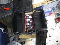
Yea. That is just more than a little ridiculous for one e bike. Five battery packs !!!!!!!! (top pic) That is what I would need for the 26" dual suspension. The LIFEPO4s in parallel with the 13S Lion and then a 10S - 8P pack which may be defective. I can not do it.

I will reluctantly need to dis assemble the solderless 6S LIFEPO4 pack and build it exactly like the one in the smaller black hyper tuff storage box with the handle. It is not much larger than a 22 AH SLA and kind of looks like one. It takes up less than half the space of the solderless pack.

The bottom pic shows the Diamondback I am not using. I could take the 1,000W motor off the 26" dual suspension and put the 1,800W brushless motor on the back and put the 1,000W hub motor on the back of that Diamondback if it will fit. I have to haul it up stairs anyway as I need to hook up the sensor less 1,000W 35 amp Greentime controller anyway.

I also have that 750W gear reduction motor laying around. I could take the Bafang off the front of the 26" dual suspension and put the 36V - 750 watt gear reduction motor on the front. A 2 kilowatt controller for the 1,800W brushless motor and 1 kilowatt 30 amp 48V brush controller for the front. Total power will be > three kilowatts @ 53V and will run off a single throttle with 50 mph gearing. :twisted:

Unfortunately I do not even have a reliable > 1,000W 53V pack let alone a 3 kilowatt pack. The 13S 7P pack is questionable. I know it wont do 1,200W Looking at = or < 1,000W :oops: So that might be a pipe dream. I have not hit 30 mph with that pack yet. Close though. Was going to put the camera in front of the meter but then had the voltage drop and flat tire.

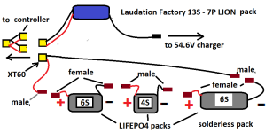
However I am still looking for feedback on the LIFEPO4s and the parallel hookup to the 13S - 7P pack. I might have to re solder all those LIFEPO4 to install heavier gauge wire but do not want to. I got too many other things I could be doing so will repost the video and my wiring diagram now as was hoping to hear from DA. If the parallel deal will not work safely I wont be running LIFEPO4 any time soon.


https://www.youtube.com/watch?v=x8sM3geHB3M


hookups.png

I am hoping DA will watch the video link above the diagram and then look at my diagram and then give his professional opinion. I actually started a new post here on ES and got feedback from a member I never saw before. However I highly respect DAs opinion as he went to college I think for electrical engineering and think he got his masters. If DA reads this I got this information from my new post.

by batteryGOLD » Jul 12 2021 4:21pm

U could get more capacity from this system by charging all this stuff to 57,6V , but...
you have to MAKE SURE that Lithion ION 13S BMS cutoff/opens circuit at 54,6V!
this way, since LithION battery is full, it keep putting more charge at LiFePO4 packs until max 57,6V

NOT recommend doing this..

if LithION pack bms does not have superior cutoff,it will put 57,6V at lithION 13S cells, meaning 4,43V for each cell. maybe still workin..

by batteryGOLD » Jul 12 2021 4:01pm

That crazy system will work fine but tricky.. take care about voltage limits details!

usefull total voltage range for this parallel working range --> 54,6V(upper lithium ion cells charger) to 40V (lower LiFePO4 cutoff voltage)

LiFePO
Minimum -->2.5x16S = 40V cutoff
Maximum --> 3.6Vx16S= 57,6V max

LithIon
Minimum -->2,7Vx13S= 35,1V cutoff
Maximum --> 4,2Sx13S=54,6V max

54,6V max voltage limited by lithium ion top limit
system cut off LiFePO4 @40V and after that maybe only 13S lithium battery keep drain solo until 35,1V ..

at math is minimum multiple common calculation..

TAKE CARE because is a parallel, LithIon battery will force LiFePO4 voltage to be tha same, if your LithION battery goes 35,1V, so there will be this voltage at LiFePO4 battery package(minimum 40V forced to 35,1V)
make sure LiFePO4 BMS will cutoff/open circuit for sure at 40V! otherwise, LiFePO4 pack will be discharged until 35,1V means 2,19V per cell (under 2.5V lower limit but maybe still safe..)

there is also an unknown behavior at Lifepo4 bms cutoff voltage limits, because x3 serial LiFePO4 batteries. since each of 3 batteries have individual bms. three serial bms's(serial bms's not recommended..) .. it would be more stable if use a single 16S LiFePO4 BMS..


think about this "boom"

make sure LiFePO4 BMS will cutoff/open circuit for sure at 40V! otherwise, LiFePO4 pack will be discharged until 35,1V means 2,19V per cell (under 2.5V lower limit but maybe still safe..)

Yea. The guy sounds like he knows a lot but he failed to read my posts as he thinks the LIFEPO4 has a BMS. Only the Lion pack has a BMS. The LIFE packs have balance plugs for each pack.

I am sure DA has his own opinion but after reading that was thinking if I use the power meter and can monitor standing and voltage SAG onboard I would be able to stop running the packs at any voltage I desire so could avoid running them low and LVC and all of that. I could run from full charge and stop at 46V for example. I am looking for a different power meter with a larger brighter screen though.

The video clearly states two batteries of different capacity in parallel will keep the same voltage during discharge. The 13S - 7P pack is rated at 20 Ah. The 16S LIFEPO4s are rated at 19 Ah. The standing voltage should be really close also if I am charging both the LIFEPO4s and the 13S-7P Lion pack thru the Lion packs charging port with the 54.6V charger.

I do not see any problems but am trusting DA to make up my mind. I do not want these packs to fail or an onboard fire. The LIFEPO4s were about $230 and the 13S Lion pack about $170 so $400 worth of batteries here. What I want to do is not simple. It is complicated unorthodox. It is not the LIFEPO4 cells I worry about as they are almost indestructible compared to Lion. It is the 13S Lion pack and what the BMS will do.

It seems though if the LIFEPO4 is being charged with the same 54.6V charger that the Lion 13S BMS will just see it as a 54.6V load and after charging there should be minimal current flow between the packs to equalize everything. I might have to use the balancer though to balance the LIFEPO4 if the packs become unbalanced as no LIFEPO4 BMS.

I have three balancers so is it ok to balance the three LIFEPO4 packs while charging or need to split up the packs and balance before charging. Is it ok to Balance the LIFEPO4 packs awhile in parallel with the Lion pack ????? I know balancing will lose some voltage as it goes from the highest cell down but then the 13S Lion pack should add that back to the LIFEPO4s and it would all equal out. I just do not know. I am just guessing.

If charging them separate and balancing the LIFE when NOT in parallel with Lion I just need another 54.6V charger. Probably a better idea as then it is less complicated. ??? They will discharge together and charge and balance separate.

I hope DA posts.

Thanks.

LC. out.
 

Attachments

  • download (10).png
    download (10).png
    38.2 KB · Views: 322
  • download (11).png
    download (11).png
    61.6 KB · Views: 322
No!
You do not want to parallel Lithium Ion (LiCoO₂ or variants) and Lithium Iron (LiFePO₄).
A recipe for disaster in oh so many ways.

If you need to experiment ... ?
It is much more safe/feasible paralleling SLA and LiFePO₄.
Still stupid ... but less liable to destroy anything-everything.
 
This server was down for about 18 hours. I got a weird error message. It could just be general maintenance of the server.

OK. First I want to thank DA. for his advice regarding paralleling Lion with LIFE. It was not really the answer I was looking for but probably will save me a lot of grief later on if I did try it.

I also want to thank Backlight for letting me know that there is no way the 16 gauge wire would work for heavy discharge > 1 kilowatt and up to 3 kilowatts.

latecurtis wrote: ↑Jul 10 2021 8:00pm

The 1,800W brushless motor has a 1,500 watt 35 amp controller. 14 or 16 gauge wiring and a 40 amp DC breaker.
It’s a miracle you haven’t started a fire.

For a 40A circuit protective device you should be using 8 gauge.

If you’ve wired entire packs incredibly undersized wiring no wonder you’re having problems. It’s not just the main + and - from the pack, it’s all the series and parallel links.

I did research and found this video.


https://www.youtube.com/watch?v=0DhzWPoSYoQ&t=44s


100 amps thru 10 gauge wire. It did not get really hot. The 12 gauge did and obviously the 24 gauge caught on fire almost instantly. Since the maximum amps I will be using is about 50 or 1/2 what was in that video I decided on 10 Gauge wire but not any wire. Appliance grade rated at 600 volts. Yea. The good stuff. Not cheap 10 gauge car stereo wire. :lol:

I went to Harbor Freight and got a 100 watt solder gun. I also ordered a Weller professional solder iron with screw driver tips.

I went with 10 gauge wire from Home Depot. I got a 25 foot roll and will be replacing all the 16 gauge with 10 Gauge.

On the top of the cells (positive) I will need the 130C tape and will wrap some around the wire also as I will be using a single piece of bare wire across the top and bottom of the K2 energy cells. I can try and keep some of the insulation on the wire also but we are talking about 5 solder joints in a 6 or 7" piece of wire top and bottom. I might not be able to.

I bought insulated wire as all the series connections and wires going to the power/bullets will now be 10 gauge. It should be good for about 3 kilowatts for 20 or 30 seconds and around 2 kilowatts until the battery voltage runs low.

The wire is 600 volt and rated for appliances. It did not give a power rating in watts or amps but looks better than the wire used in the video above. Therefore if I pull this off I will have a 3 kilowatt battery as soon as I order 1 more box of those K2 energy cells. I will be building at least one more 6S - 5P pack.

I will be re soldering both the 6S and 4S pack with the 10 gauge wire and then the solderless pack which also has 16 gauge wire for all the series connections. Maybe some 14 gauge wire but do not think I used 18 gauge. I bought 14 gauge before at Home Depot but ran out so had to use 16 gauge from Wall-Mart I think. I will have to remove all that which means un - soldering which I never did before. :roll: At least I have a 100W gun now so should go smoothly as not enough heat wont be an issue.

I will soon have 16S total for 53V and 2,650 watts as 53V * 50 amps = 2,650 watts.

When I get a third 6S - 5P pack built it will be 60V and 60 * 50 = 3 kilowatts. I have the 40 amp breaker for the 1,000W 26" hub motor but will need a 60 amp breaker for the 3 kilowatt brushless motor later on when I build the Haro V3.

When I am done and have the two 6S and the 4S pack finished I want to do a capacity test as well as a discharge test starting with the 4S LIFEPO4 pack. I am looking at 150W / 13V LIFE and then 300W / 13V LIFE with the 10 gauge wire.

150W / 13V = 11.5 amps. 300W / 13V = 23 amps.

I bought those 150W heaters last winter DA recommended. :lol: They did not work very well. Only paid 11 bucks each for them though. I figure perfect for capacity and discharge tests. I just need a cheaper but accurate set up like the video for measuring the heat of the wire. The capacity will need to be calculated but will let me know if I damaged the cells or not soldering.

After that I might get a sub woofer and amplifier rated at 750 watts RMS and run it off the 4S - 13V pack for 57 amps. I can stop if the wire gets too hot. I will need a way to measure the temperature of the wire which is rated at 105 degrees C which is 240 degrees Fahrenheit.

That may be a few months down the road though as am on a budget and looking at the 1,000W 26" hub motor now for < 1,500W. To be honest the 3 kilowatt motor and Currie might be a mid winter project.

I have been wanting to build that speaker box for about 20 years now but with two 12" woofers in isobaric push pull mode.

https://billfitzmaurice.info/AutoTruckTuba.html

download.png

Basically what happens is two 12" speakers will sound like four 15 inch subs or two 18" subs and take up less than 30% of the space. I was seriously into home and car audio and ran two 18: subs isobaric in the back of an 82 Cadillac Deville back in the mid 90s listening to the Wu Tang Clan.

Then I got old but a 750 or even a 500W amp and that set up would seriously smoke two 15" subs and a 2,000W amp today.

I might just use the 3 LIFE packs for 53V and run the 1,000W hub motor and the 1,800W brushless motor and build a whole new 60V pack for the 3 kilowatt motor and use 8 gauge wire for that.


Thanks for the good advice. It is time for me to get to work.


LC. out.
 

Attachments

  • IMG_0479.JPG
    IMG_0479.JPG
    347.9 KB · Views: 307
  • IMG_0484.JPG
    IMG_0484.JPG
    291.2 KB · Views: 307
  • IMG_0485.JPG
    IMG_0485.JPG
    321.8 KB · Views: 307
Yes Neptronix explained what happened in a post in the General Chat, the server hard drives got full.
https://endless-sphere.com/forums/viewtopic.php?f=1&t=112631

How many soldering irons have you purchased in total?

Oh its about time, hopefully everything will go smoothly and onto the next problem, perhaps a chain guard oh wait wait, its actually more speed right, you are addicted, you need to beat that go-kart.

latecurtis said:
This server was down for about 18 hours. I got a weird error message. It could just be general maintenance of the server.

It is time for me to get to work.
 
Oh its about time, hopefully everything will go smoothly and onto the next problem, perhaps a chain guard oh wait wait, its actually more speed right, you are addicted, you need to beat that go-kart.

Well yes I do like to beat gas with electric whenever I get the chance. I really don't like gas and all that noise , bad smell and air pollution so like to prove electric is better and would love to see people with go carts like that strip them down and scrap the metal and order a 3 kilowatt motor or two and order LiPo or LIon. :lol: It would help out the environment also which we all realize is becoming more and more important considering the heat waves and all.

However there is a different reason also. A few members like DA and some others have been very patient with me over the years and I kind of need to prove that all those efforts are not in vain. I took about a year and a half of electrical technology in the community college back in NY. 95 and 96 and 2005 and 2006. I need 14 credits for associates degree. I might even return.

I should have known better to use 16 gauge wire for a 2 or 3 kilowatt battery from the start. I just was not thinking. I was thinking 1,500W for a 16 gauge extension cord. Not sure where I even got that number. I remember sitting at college and there were complex equations to measure the resistance in wire. I did remember that pie was somewhere in it but completely forgot most of that.

I do know > 8 gauge wire for car batteries and the more amps the thicker the wire. I used 16 gauge speaker wire for 400 watt stereo amps and for a lot of e bike builds back in NY and went 30 mph and 1,000W many times so was not thinking. I bought an 1,800W motor here in Ohio and the 3 kilowatt motor. I should have realized it was time to upgrade my wiring. Thanks to Blacklite I now realize that.

I kind of want to be like the guys on you tube that make videos testing wire , capacity , voltage and discharge. I want to excel to the level I should already be at considering my age and tech. background. I started college back in 1995. It is 2021. I should be right where DA. is right now but I did not finish college like he did. Also I did not start a successful business.

I just went from one hobby to a different one. In the 90s and early 2000s I wanted to build and design custom loudspeaker systems. car and home. I read books like advanced speaker design by Vance Dickenson. I went to Radio shack three or 4 times a week. In the mid 80s had four 15" woofers with four 12" woofers on top plus super power horns 110 DB and 6" midranges. A 100 watt RMS and a 65 RMS receiver with a 12 band EQ with bass expander and a 10 band eq. An 80W Laconic on the top. 8" fans to keep the amps cool. It looked like a Christmas tree. Was about 6 feet of electronic equipment. Not 4 channel in the 80s or surround like today but 8 speaker systems. All 4 corners of a 24 by 10 foot living room speakers stacked about 6 feet high. :lol:

My neighbors hated me and the the cops were at my door almost daily. I got kicked out of a lot of apartments. I was into car audio. I listened to Metallica and Megadeath , Slayer , carnivore ect. It was radical. The only reprieve they got was I went to jail a lot for breaking in houses and beating up cops. :lol: :lol: :lol:

Like I said I got old. I changed and got into computers in the mid 2,000s and 20010s Also custom aquariums but got the e bike bug really quick since 2013. So basically with my background I should be the go to guy people go to for advice building e bikes. Not the other way around so I feel like I have to do better.

I must learn from my mistakes and start listening to the advice I have been given and hopefully not too far down the road be doing you tube videos on the upper level. Not like the ones in the past but much better. Soldering , installing motors and those GOOD professional builds like tomjasz keeps trying to drill in my head.

Thanks.

LC. out.
 
So long as you dont beg for thumbs up, smashing the like button, clicking on the notifications button and making a comment in your youtube video's. I just hate it when youtubers beg. I rarely ever long into my Youtube account. I think I logged in 2 years ago to make comments in a video then I deleted the comments months later.


I must learn from my mistakes and start listening to the advice I have been given and hopefully not too far down the road be doing you tube videos on the upper level. Not like the ones in the past but much better. Soldering , installing motors and those GOOD professional builds like tomjasz keeps trying to drill in my head.
 
The 10 Gauge wire wont solder to the cells . I used the high temperature tape and had the solder gun as well as the 60 watt iron both at the same time and the thick 10 gauge wire dissipated the heat and the solder did not stick to the cell. The insulation and 10 gauge wire is designed for high temperature and 240 to 600V appliances drawing 20 or 30 amps I think. Totally impossible to solder it to any cell.

The solder gun is a piece of garbage. I am not wasting my time and gas taking it back. I am simply throwing it out. I wasted a lot of solder trying to do the impossible. Solder 10 gauge wire across five 26650 cells. It is not happening.

I also figured out that the original first way I soldered cells was the best way by far. I was trying to solder a single piece of wire to a row of cells kind of like a bus bar. It don't work as well. It don't work at all with 10 gauge wire. I had a little solder left so used the 60 watt iron that at least melts solder and even with a tip that is completely shot had some success. In fact I did it that way in NY and on several small 3S and 1S Lion packs here about a year ago.

IMG_0486.JPGIMG_0487.JPGIMG_0488.JPG

I am out of solder. Basically I do not need to solder 10 gauge wire to a cell doing it this way. I just need some good flux and solder those five wires to the 10 gauge wire on the top and the bottom for the series and power connections.

What I need to do tomorrow is put some money on my card and order a bunch of those screw driver tips for that Weller 100 watt solder iron I ordered. Basically that Weller is my last and only hope to get these LIFEPO4 cells to amount to anything. The large tips and Quality name brand iron should turn the tide in my favor. That and a lot of liquid tape and thin strips of electric tape. The pack must fit in those hard plastic black Hyper tough storage boxes or it is a deal breaker. I came SOOOOO close to throwing the LIFEPO4s in the dumpster before going back to my original soldering technique. The one that works.

I am now about to do an internal resistance test on all the cells I heated up by soldering and some of the cells I did not solder and compare the numbers. The way I see it is if the cells were damaged by heating them up then they should have a higher internal resistance. Oh and I got the meter to give stable readings. I just have to push in on the test terminals. I am now getting consistent readings.

Well there seems to be no damage to the cells I soldered. Also what DA. said makes sense to me now as I did a voltage check. All the cells I DID NOT solder. The 5 cells I removed from the solderless pack are around 3.4V as they were balanced charged two or three times with the LiPo charger. The cells I soldered I think I charged one time or no times. They are all very close to 3.3V.

DA said the internal resistance raises with voltage. The video clearly shows 17 to 19 consistently on the cells that are 3.4V never soldered and the soldered cells which are all slightly lower , around 3.3V are slightly lower in internal resistance.

It is not that DA was right that makes me happy. He usually is about 95% of the time. It is the fact that my meter is accurately measuring internal resistance. Maybe it is not 100% accurate but it seems to be giving consistent readings therefore making it a useful tool in my e bike workshop.

The other thing that makes me happy is that it looks like I did not damage the 26650 cells heating them up. At least something went my way as that new $30 solder gun sure did not. I cant believe Harbor Freight sells such garbage. It is like going back to a 30 watt Wall-Mart iron. Not worth the wear and tear on my old van to take that back. Also I might end up punching someone in the face if I don't get my money back. It is going in the dumpster tomorrow.

I only have a few days to go and will have a good 100 watt iron and extra tips. One of the reasons I changed my solder method was I did not want to deal with the extra space the wires took up. Soldering is just one step in building packs. The way the cell banks are stacked to fit the container they will be in is s design issue concerning space. I see why the tabs and spot welding is popular. Space management.

Now I need to figure out how to squeeze all those extra wires in the black Hyper Tough boxes. Also I prefer NOT to cover up the solder terminals. I would like to see them all in each bank so if a solder joint came loose I could just fix it instead of wondering if all is well or spending hours checking each bank for voltage and capacity. Any suggestions will be appreciated.

Thanks.

LC. out.


https://www.youtube.com/watch?v=4BzwiQ5hhmk


Thanks.

LC. out.
 

Attachments

  • download (5).png
    download (5).png
    20.7 KB · Views: 250
Of course ... ?
You used the "lead free" solder that came with the soldering gun? (warned against so many times)
and
Did not pre-tin the cell and the wire? (simple steps that insure good adhesion and reduce heat transfer)
and
Heated soldering gun too hot, so solder won't flow onto tip? (Tip will actually repel solder, severely limiting heat transfer!)

Do you keep your tip clean? Should be smooth and glossy with a nice coat of solder after wiping on moist sponge. Oops, sorry, almost forgot you burn and char your tips so solder won't even stick to it.

New tip
10Awg stranded wire should be squashed flat to allow proper heat and to create larger contact area.


Sorry everyone!

Created, in this thread, the last post before the system malfunction. Reopened post to edit some punctuation and wham ... system error!
 
Well, glad to see you will finally be working with the proper temperature soldering iron!

file.php


You accidentally(?) ordered the Weller with the fixed 700℉ temperature ( 371℃).
This should be the ideal temperature for lead based solders. (will not work well with "lead free" solder!)
Your continual insistence on using substantially higher, toxic, less effective, damaging, dangerous, temperatures frustrated me to no end!

Though, no reason for all the extra tips! At your new, enforced, "proper" temperature, a tip can last for years.
 
Well The new 100 watt gun I bought today at Harbor Freight is lucky if it can even melt solder. It is a complete hunk of junk. And I used the solder I had first before the solder that came with the gun.

I really just wish I could have sent you the cells DA and got a professional pack built with a BMS. I would have sent you a money order and paid for shipping.

I can probably get it done but it is taking up way too much of my time. I got 3 flat tires, I still have not re built the Giant Roam with the e bikeling motors and need to install that Greentime controller for the 26" direct drive. Plus I want to do something with the LTOs. The Currie has two 36V motors front and rear so 15 - LTOs would do some justice there.

My Weller 100 watt iron is on the way with those screw driver tips. I am not going back to attempting to solder a 10 gauge wire to the top and bottom of these cells. Unless you are willing to build them your way and I send you a money order I will have to solder a wire to the top and bottom of each cell and do all the series and power connections with the 10 gauge wire. I will have to scratch my head coming up with a way to stack and a container to fit them in with all those wires.

It is almost impossible to find good solder and striking gold is more likely than finding flux so a link to the best solder and flux for soldering the wires together would really help. I run out of solder a lot so need a large roll of that lead based stuff. I am about to crash. Been up all night but will check this post when I wake up later this afternoon.

Let me know and thanks.

LC. out.
 
latecurtis said:
It is almost impossible to find good solder and striking gold is more likely than finding flux so a link to the best solder and flux for soldering the wires together would really help. I run out of solder a lot so need a large roll of that lead based stuff.

60-40 rosin core solder wire 100g ~ 100g = 4oz 200g = 8oz 400g = 1lb ... 1.0 - 1.2mm recommended.

Flux
 
Thank you.

I will need to put a few bucks on my card and will be good to go. I just woke up. I did not drink alcohol either but ate a piece of carrot cake and a couple oatmeal cookies before I crashed out this morning. It put me out all that time. I got type 2 diabetes. Also some weird sleep condition where I sleep better in the afternoon than any other time of the day. I have to get up like every hour or so to drink water and let some out. It is my body de toxifying itself from alcohol or too much sugar. My sleep is never steady. I wake up at least 5 or 6 times in 7 or 8 hours.

Drinking coffee now.

https://www.youtube.com/watch?v=ublFs7IU05c

Is that video for real ????????? Is spot welding really that simple ????? The big thing I was concerned with was protecting the positive tops of the cells from the metal strip. I did not even know they make rubber rings to put on the top under the metal strip. I have not really watched many videos doing that.

Mabye I should get a spot welder then. I can still use my 100 watt iron and solder and flux to solder the series and power wires but for the cells spot welding is a much better option if it is that easy.

Are all spot welders as easy as that ? Do they have the protective rings for 26650 cells ????? That is a big deal for me. If so I think I should switch to spot welding then. Especially for 26650 cells. I could then build a pack like 18S - 5P LIFE in one day. 5 or 6 hours in the e bike workshop.

What are the power requirements for spot welding. Is his welder like $1,000 bucks or are they cheaper and work just as good.

It may be the second video I saw on spot welding. I was just looking at soldering videos. That and those videos where they install 775 motors and the new e bikes that have came out in the last year.

https://www.amazon.com/gp/product/B07MZP2BK6/ref=ewc_pr_img_1?smid=A2RB21RUGRFV4T&psc=1

download (12).png

I found that on Amazon. $144 WITH tax. Free shipping . :D


Please let me know. I do not want to order junk ???????????????? It does not say if it will do 26650 cells ?????

Thanks.

LC. out.
 
Status
Not open for further replies.
Back
Top