New Kelly pseudo FOC controller series

just came home and started to work on it :)
not installed on the bike but on my work bench to see if the android app works.
first of all i had to install phase wire connectors, and did cut off the screw terminals (still left on the battery wires in my picture below). my trusted 5.5mm gold bullets, good for up to 100A. and i must say i'm impressed. this is the first controller with adequate battery/phase wires. they just fit into the goldies perfectly fine. soldering the battery wires to my xt60 connector will be a challenge. the wire looks like a #8-10awg. well done kelly! con: they are very stiff and not fine stranded, so hard to bend. but that is only an issue during install.
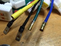
IMG_0046.JPG
now for the bad part. :( the android phone with the otg cable and my regular usb<->rs232 adapter DON'T work. just as fany from kellycontroller said. so it seems you really HAVE to buy this z-tek usb/serial converter. i already ordered one, but it will take two mode weeks to arrive. so i will have to wait with further testing.
 
Some USB-TTL adapters are different than others. No idea if the app looks for the hardware ID of the device or if it's a TTL voltage level issue on the converter. I bet we can find alternatives that are cheaper eventually. I had similar issues with my BMW diagnostic cable and USB converters; some devices require say, +-12V TTL signalling, some +-5, some +-3.3; depends on what the Kelly requires on it's serial line.
 
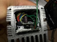
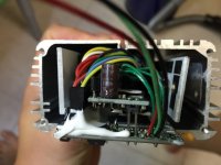
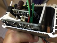
i was so curious, so i had to open all screws :) i wanted to know how many FETs, what size the pcb has etc ...
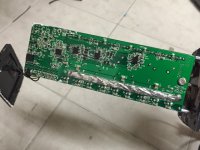
so here are some pics. quite a lot of fets. if i counted right, those are 18 FETs. so quite a big number. this controller will for sure deliver some serious amps. i just don't understand why the smallest controller has the biggest high sink. the bigger controllers don't have this enormous fins. i can't imagine that the use different FETs - would be a stupid idea to install cheap FETs and install a big heatsink.
i will install this in a low profile aluminium case over the winter. the PCB's height incl components is less then 40mm. PCB is 140mm long.
here are some pics:

IMG_0047.JPG
View attachment 2
View attachment 1
IMG_0050.JPG
 
Best I can guess is that they might generate higher heat levels since they have to do more FET switching to get true sine waveforms? Might generate more losses and therefore require better cooling. Either way, I like to see better heat shedding capability. We'll see how these play out. Could also just be a new controller enclosure format for the newer design. Clearly they are trying to maximize density by compacting the controller boards as much as possible. The more dense you make it, the more efficient your heat-sinks have to be. How much did you pay including shipping again?

EDIT: Is that a JTAG port top left in the last picture?
 
Kodin said:
Best I can guess is that they might generate higher heat levels since they have to do more FET switching to get true sine waveforms? Might generate more losses and therefore require better cooling. Either way, I like to see better heat shedding capability. We'll see how these play out. Could also just be a new controller enclosure format for the newer design. Clearly they are trying to maximize density by compacting the controller boards as much as possible. The more dense you make it, the more efficient your heat-sinks have to be. How much did you pay including shipping again?

EDIT: Is that a JTAG port top left in the last picture?
no. this is 2 leds.
 
the board looks strange to me with the phase wires attached on one side somewhere on top of the FET's. i wonder how this works.
on the other side there are many caps and also small ceramic types. the power trace on bottom is beefed up. nice to see.
izeman, are you going to also test it with a DD hub (i think of your klein mantra if you still have it)? It would be nice to see how it performs but only if you have time and if its not to much work :)
 
Does it have analogue brake signal input? I see that dedicated port can be used for measurement of temperature, so it has ADC. But does it have a function for variable braking?
Or can this function be achieved with "joystick" feature?
 
izeman thanks for the effort on the internals , thats the most serious case ive seen, just for interest kelly now have got the windows program software going.
I requested they change there amp ratings from phase to battery amps and a kw rating ... will be interesting to see there response.. my gut tells me they wont change.
 
would be interesting to know the real continuous rating of kelly controllers in general.
when i have worked with the KBSX controllers, fany has explained like this:

as example one controller is rated for 120A phase current (as also the name of the model tells us) and 50A continuous:
in the software we can set phase current to 100% but battery current normally to only 70% maximum
ok, now a calculation with this 120A controller:

phase amps set to 90% so 120A x 0,9 = 108A
battery amps set to 50% so those 108A x 0,5 = 54A

during acceleration the phase amps will drop quickly so it should be within this 10sec boost time in most applications, but what happens if we climb a steep hill and the motor wants lets say 80A continuos for much longer time? will it than cut back to only 50A after exact 10sec?

fany has this not explained me :)

IMO its a bit stupid to make this time related. If it would be temperature related it would make much more sense.
 
madin88 said:
as example one controller is rated for 120A phase current (as also the name of the model tells us) and 50A continuous:
in the software we can set phase current to 100% but battery current normally to only 70% maximum
ok, now a calculation with this 120A controller:

phase amps set to 90% so 120A x 0,9 = 108A
battery amps set to 50% so those 108A x 0,5 = 54A

during acceleration the phase amps will drop quickly so it should be within this 10sec boost time in most applications, but what happens if we climb a steep hill and the motor wants lets say 80A continuos for much longer time? will it than cut back to only 50A after exact 10sec?

your equation seems wrong to me. it's right that kelly rates their controller's PHASE amps maximum boost. so in my case (KLS6018S) this is 240A peak and 100A continous. for those sine-wave controllers you can set phase and battery current to 100%.
so phase current can go up tp 240A at start and then goes down when speed goes up and voltage to the motor reaches battery voltage. at battery voltage the phase amps should be able to stay at 100A continous. at least this is the theory. we will see. and i will start with all settings set to 100% and will do limiting by my CA.

btw: the PC config software is out since today!! http://kellycontroller.com/mot/downloads/Kelly%20KLS%20Configuration%20Program.zip
 
Ok but if battery current can be set to 100%, would this mean it will drain also up to 240A from the battery? Or is the battery current percentage related to the 100A continuous rating?
and does it really reduce current after 10sec to 100A?

one thing is sure: on KBSX controller it was like in my previous post (as also fany explained). the numbers the attached CA did show have confirmed this.
 
today i installed JST connectors to connect it to my motor and throttle. the battery/phase wires are VERY stiff as already mentioned. even though they are absolutely up to the task i guess i will change them for super soft silicone wires as the original ones are very hard to bend.
what shall i say: it was a pretty straight forward install. connect phase wires, hall wires, throttle, find a correct combination and you're set. i was expecting some kind of "auto learn hall combination", but nothing like that - or i didn't find it.
there is some "angle sensor identification" but i don't know what it is for.
also compared to those new grin tech controllers, i must say, there is not a lot to configure. you can set throttle range, max current, max speed and some other trivial things. but nothing "sine wave" or "foc" related. on the other hand this may be good, as i wouldn't know what to set anyway :)
so that's it for the moment. the motor is running, but i didn't test the controller on the bike. this may take some more time.
 
i tested the controller on my mid-drive bike. and i must say I'M SOOO HAPPY.
this controller REALLY ROCKS. it's SUPER POWERFUL, SUPER SILENT and SUPER SMOOTH! i couldn't ask for more. maybe it's too powerful for my motor, as 240A phase amps may burn the windings.
it was only a few km test ride, but it was enough to say, that this is BY FAR the best controller i ever had. after i removed the controller and connected the old kelly again i was really shocked about the motor noise. all i hear now is a very little noise that comes from the internal gears and chains. the motor itself may only contribute very little to the noise. now the bike is as it should always have been. i can ride through the forest and may be seen as a regular biker. before the bike had a very high pitched noise that was not nice.

i also noticed that the bike is as fast as NO LOAD speed. so with lifted rear wheel i get the same speed as on flat going WOT. but maybe i'm wrong. i will have to test again to verify that.

there still are some things to solve:
-) best battery/phase relation.
-) max phase current (battery current will be regulated by the CA profiles)
-) the motor doesn't stop if i release the throttle. it takes some time to come to a stand
-) going WOT on the bike stand (rear wheel lifted from the floor) makes the motor pump. so it revs up and down and up and down again. this may be some controller internal mechanism that stops current/rpm from overshooting, as it doesn't occur while riding.

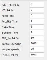
and there are some paramters that i don't really understand and that are not explained in the manual. especially the last three are totally unclear.

Capture.JPG
 
maybe someone can help me finding an 15 or 18fet "infineon" controller case where it want to fit that kelly controller in.
i posted my request in the "wanted items" section, but i guess noone reads that. there must be tons of broken old controllers which could donate their case for the good :)
 
good to hear it performs well and you are happy with it. i had a blown 18fet lyen but unfortonately i have sent it to someone from here..
what about buyable aluminum cases from conrad shop for instance? they have lots of different sizes.

these settings i think are releated to FOC like timing stuff but lets see. hopefully one is for field weakening.
same no load rpm "out of the box" sounds nice.
 
madin88 said:
good to hear it performs well and you are happy with it. i had a blown 18fet lyen but unfortonately i have sent it to someone from here..
what about buyable aluminum cases from conrad shop for instance? they have lots of different sizes.

these settings i think are releated to FOC like timing stuff but lets see. hopefully one is for field weakening.
same no load rpm "out of the box" sounds nice.
conrad hasn't got the ones i want, and aliexpress sellers have them, but they want 30 pcs min for custom length. a bit too much.
circuit was so kind to sell me one of his spares. no i have to find a way to squeeze this pcb into an infineon's case :)
i'll update the thread here.

i'm in contact with fany and they are very responsive and have really great support. i guess together we can sort out all things needed.
 
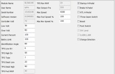
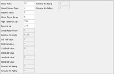
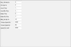
for those interested, and that don't have the controller yet to try out the software i made this short review. when you click a changeable field/value there is a comment field explaining the setting. this is what i c&p below. those are not MY words.

kls_vehicle.JPG
Low Volt: The min voltage of reporting this fault - Range 18~80
Over Volt: The max voltage of reporting this fault - Range 18~80
Current Percent: Phase Current Percent. Range: 20~100
Battery Limit: Battery Limit Current, Limit the max value of Battery Current. Range: 20~100
Identification Angle: If read data is 85, the normal operation of the said. In 170, and then restart the controller will automatically into a state of identification Of Angle sensor, after the succes of the identification will be automatically reset to the data in 85, the state of the normal operation. Range: 85~170
TPS Low Err: Hall active pedal, if lower than the value, report the fault of TPS Type. Range: 0~20
TPS High Err: Hall active pedal, if higher than the value, report the fault of TPS Type. Range: 80~100
TPS Type: TPS Type, 1:0-5V, 2:Hall active pedal. Range: 1~2
TPS Dead Low: TPS Dead Zone Low. Range: 5~20
TPS Dead High: TPS Dead Zone High. Range: 60~95
Max Speed: Max Speed [rpm]. Range: 0~10000
Max Fwd Speed %: The forward speed of the percentage of maximum speed. Range: 20~100
Max Rev Speed %: The reverse speed of the percentage of maximum speed. Range: 20~100

kls_motor.JPG
Motor Poles: Motor Poles, The pair pole number*2. Range: 2~128
Speed Sensor Type: Speed Sensor Type, 2:Hal, 3:Resolver, 4:Line Hall. Range: 2~4
Resolver Poles: Resolver Poles, The pair pole number*2. Range: 2~32
Motor Temp Sensor: Motor Temp Sensor, 0:None, 1:KTY84-130 or 150. Range: 0~1
High Temp Cut Out °C: Motor High Temp Cut Out, nominal value 130°C. Range: 60~170
Resume °C: Motor High Temp Resume Temp, nominal value 110°C. Range: 60~170

kls_control.JPG
RLS_TPS Brk %: RLS TPS Braking Percent, the percent of Releasing Pedal BRK in max braking. Range: 0~50
NTL Brk %: NTL Braking Percent, the percent of Neutral Braking in max braking. Range: 0~50
Accel Time: Accel Time, the time of TPS Torque from 0 to max, accuracy 0.1s, 5 is equal to 0.5s. Range: 1~250
Accel Rls Time: Accel Release Time, the time of TPS Torque from max to 0, accuracy 0.1s. Range: 1~250
Brake Time: Brake Time, the time of Brake Torque from 0 to max, accuracy 0.1s. Range: 1~250
Brake Rls Time: Brake Release Time, the time of Brake Torque from max to 0, accuracy 0.1s. Range: 1~250
BRK_SW Brk %: BRK_SW Braking Percent, the percent of BRK_SW in max braking. Range: 0~50
Torque Speed KP: Speed Percent Kp in Torque Mode. Range: 0~10000
Torque Speed KI: Speed Integral Ki in Torque Mode. Range: 0~500
Speed Err Limit: Speed Error Limit in Torque Mode. Range: 50~4000

most settings are self explaining, but i don't understand why they still use abbreviations in the comment field which should be there to make clear what the value is about. there also is some "standard value" missing. so once you change it and haven't written down the original values they are lost. i didn't find a "reset" button or some way to save profiles.
so the software still has some room for improvement.
feel free to comment or ask ...
 
izeman said:
i tested the controller on my mid-drive bike. and i must say I'M SOOO HAPPY.
this controller REALLY ROCKS. it's SUPER POWERFUL, SUPER SILENT and SUPER SMOOTH! i couldn't ask for more
Nice to hear that, I am also very closely looking at buying one. Have you tried other controllers, like adaptto, sabvoton or similar and could compare the smoothness?
 
izeman said:
today i installed JST connectors to connect it to my motor and throttle. the battery/phase wires are VERY stiff as already mentioned. even though they are absolutely up to the task i guess i will change them for super soft silicone wires as the original ones are very hard to bend.
what shall i say: it was a pretty straight forward install. connect phase wires, hall wires, throttle, find a correct combination and you're set. i was expecting some kind of "auto learn hall combination", but nothing like that - or i didn't find it.
there is some "angle sensor identification" but i don't know what it is for.
also compared to those new grin tech controllers, i must say, there is not a lot to configure. you can set throttle range, max current, max speed and some other trivial things. but nothing "sine wave" or "foc" related. on the other hand this may be good, as i wouldn't know what to set anyway :)
so that's it for the moment. the motor is running, but i didn't test the controller on the bike. this may take some more time.


The instructions I got was to set the "Identification Angle" to 170 and write to the controller. Turn off then on. It will then to an auto learn... wait until it has finished and the LED start flashing. Turn off then on. Read the settings again and you should see the "Identification Angle" is some other value.

That is the extent of the functions of Auto Learn.
 
Back
Top