No F*ing idea Friction drive

ok, so to simplify this for a layman i assume i am putting a amp meter on the battery positive line and running the motor very slowly at a constant speed and shifting the Hall ring about 5 degrees around the motor to see where i get the lowest current draw? :mrgreen:

Oh and battery and phase current is stock for the controller, 70amp and 30, so fairly low. Anyone have any recommendations for what i should limit everything to with the motor i am using realizing that i am running it on 12S.
 
OK, played with the hall positions, my setup had the motor drawing 4.8amp with no load with the volts limited by the controller to 30%, so roughly 15V to the motor. I managed to find a lowest point of 3.8A and the highest was 9A before the motor wouldnt run. Still cuts out over pretty much the same RPM so i might have to mod the controller using the ideas posted in the thread that Gwhy linked. I double checked my hall ring and they are at 120 degree intervals +/- 1 or 2 degree i hope thats accurate enough.
 
I have the same motor, running off a 85A Turnigy ESC.

Here is my no load readings for just turning the motor over at full throttle for various voltages.

2S / 8.21V / 1.87 Amps
3S / 12.51V / 1.90 Amps
6S / 24.54V / 2.12 Amps

When I have the outside of the can friction driving my wheel off the ground these are the readings

2S / 8.21V / 2.3 Amps / 22 kph
3S / 12.5V / 2.3 Amps / 34 kph
6S / 24.5V / 2.6 Amps / 69 kph

Hope that helps.

- Adrian
 
The Lyen controllers I believe can only handle 120,000 electrical rpm.
Reference: http://www.endless-sphere.com/forums/viewtopic.php?f=30&t=20840&p=304101&hilit=erpm+infineon#p304101

So:
120,000 / 270kv / 14 magnets = 31V Max before the controller can't switch fast enough.

So it can go 100% throttle on 6S
But on 12S you could only theoretically go about 60% throttle.

But I could have got that calc wrong.

- Adrian
 
Ohh thanks for listing the no load amps you are getting, i think i am going to have to check my halls again and then try all 36 combinations in case i missed one, the one that might be right.

I have solved my cut out problem, it was caused by some software limiter, i had to reflash the controller with the 18Fet controller setup and double the phase current and now it is very happy going above where it stops and does not cut out if i snap the throttle wide open. But it now doesnt go above 15V under load which gives me the idea something is wrong with my halls, either their distance around the can isnt 120 degrees or they are not setup right, i ll keep pluggin away till it works the way i want it too :mrgreen:

Aside from all that, how fast have you been able to get your bike to go with this motor Adrian? Do you think it is capable of ~50kph powering a bike with a 85kg guy weighing it down :twisted:
 
Great to hear you are making progress.

BTW You shouldn't need to try all 36 combinations. 12 should do it. Since some combinations will have the same "firing order".
If capitals are phase, and lower case are halls, then all of the following should be the same. ABC-abc, BCA-bca & CAB-cab.
This assumes the relative spacing of your halls is all spot on.

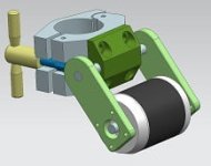
I haven't got my bike running with the little Turnigy SK 50-65 270 yet. It is just a paper concept at the moment. Here is a sneak peak of what I have planned.
Still need to fabricate a few bits at work first (the green bits in the image below). I am going for the ultimate compact light weight assist. Plan will be to clamp it on at the top of the seat tube, and have it rotate into the wheel.
This doesn't show the springs, dampening or dead stops but I think I have that sussed in a compact, and adjustable way all on the pivot shaft.

friction_drive_ver3_sml.PNG

As for will it go 50 kph. The orange line on the graph below shows the power I require on my current bike to go various speeds on the flat.
So at 50kph it is about 800-900w. Well within the power of what the little Turnigy 50-65 can deliver. I am just not sure how hot it will get doing it.
Perhaps someone else who is running this little guy can let us know.

file.php


- Adrian
 
I don't know for sure about Lyen's controllers, but the ones from Keywin (which I think is the chap Lyen buys his from) are OK for much higher rpm than you're going to see with a 270Kv motor on that voltage.
I've run a 215Kv motor at 59V (about 12,000rpm no load) and it seemed OK. 12,000rpm on a 7 pole pair motor is an electrical rpm of 84,000, so still well inside the limit of around 120,000.

BTW, the calculation to work out the maximum motor rpm from a given electrical rpm limit is:

Motor rpm limit = electrical rpm limit / number of magnet pole pairs

In this case, that's 120,000 / 7 = 17,143rpm, or a supply voltage of just over 60V for a 270Kv motor.

Jeremy
 
Wow cad drawings and a plot graph with power vrs speed, you sure are doing alot more planning then i ever did, should mean your guaranteed to have everything work first go :D Wish i could be bothered doing plans, i tried.....30sec later i was like frock this...wanders off to watch a movie :roll:

back to playing with the bike :twisted: I have a no load draw of 4.2A currently at 12V which is not cool :(
 
Bluefang said:
Wow cad drawings and a plot graph with power vrs speed, you sure are doing alot more planning then i ever did, should mean your guaranteed to have everything work first go :D

No way. As Jeremy and Luke keep pointing out, I have no idea what I am doing when it comes to the inner workings of the motors. :roll:

Much better to dive in and do it, than stuff around in front of the computer. Keep up the good work.

- Adrian

P.S. Thanks again Jeremy for correcting me. :oops:
 
Ok, my hall ring has a diameter of 53mm so each section between the halls should be 51.5mm cause the halls are 4mm wide, now i have 2 sections that are 51.8mm and one that is 50.8. Is this going to be enough to throw out my halls?

I am a bit stumped as to why i cant get the motor to run over like 18V. the controller just seems to stop adding power then, i am also having trouble having the motor start up sometimes, most of the time it will just kick in when i want but sometimes it needs abit of movement to start.. Also is it normal to have the throttle only kick in after turning the twist grip like half of its rotation? I bought the throttle and controller from Lyen so they should work well together. Any suggestions would be great, normal problem solving i am great at, electrical problem solving i suck at.


Really wish i had bough a bigger motor so i could just put the halls in the slots and be done with it :roll: Plus it could make me go faster :twisted:
 
Bluefang said:
Ok, my hall ring has a diameter of 53mm so each section between the halls should be 51.5mm cause the halls are 4mm wide, now i have 2 sections that are 51.8mm and one that is 50.8. Is this going to be enough to throw out my halls?

I am a bit stumped as to why i cant get the motor to run over like 18V. the controller just seems to stop adding power then, i am also having trouble having the motor start up sometimes, most of the time it will just kick in when i want but sometimes it needs abit of movement to start.. Also is it normal to have the throttle only kick in after turning the twist grip like half of its rotation? I bought the throttle and controller from Lyen so they should work well together. Any suggestions would be great, normal problem solving i am great at, electrical problem solving i suck at.


Really wish i had bough a bigger motor so i could just put the halls in the slots and be done with it :roll: Plus it could make me go faster :twisted:

It maybe enough to throw it all out as you have 2 sensors in the wrong places ( each gap should be identical ) I quickly ran through your numbers and the gap between sensors should be 53.5mm.. ((53xPi)/3)-2=53.5 for 120degrees spacing

Edit: :oops: I got it wrong, scrap that...
edit: Nope you were right ((53xPi)/3)-4=51.5 for 120degrees spacing (Gap between halls)
 
Ohh well, tomorrow i ll go buy some acetone and dissolve the super glue and rebuild the mounts for the hall sensors. this time i ll measure everything properly rather then measuring once and relying on pot luck for it to be ok.
 
Im not sure now if this error would be enough to give you the symptoms that you describe but would more likely suspect one of the halls not working as it should ( are they all facing the same way around the ring ?)

Edit: the motor should start to run as soon as the throttle starts to turn ( but you could just have a dodgy throttle ). but you defo should not have to help the motor start from stopped ( this is what makes me think it is a hall not doing its thing )
 
I'm amazed at your skill...you still have your GLASS top workbench...do you have a plywood spare for backup...just in case? Nice home build...maybe a little fix on the denutter case corners.
 
Dooh, my hall sensors are firing very well. I had my father around with his Osciliscope and all my hall sensors are triggering.

Problems i have with it atm, The controller is set for the 18Fet rather then the 12Fet flash settings to stop the cut out, it cured the cut out problem of really hard throttle acceleration but seems to be causing a limit to the voltage i can supply, its there some other setting i need to change?
1) Currently my controller does not want to push the motor past 5.6V full throttle on either setting of my 1,2,3 switch ends up with the controller only outputting 5.6V to the motor.
2) I have checked all 36 combinations of halls and phase wires(listening to some good music) and found only 2 setups where the motor ran good out of each lot of test, 1 back and 1 forwards, both ran equally well so i would assume that means my halls are in a ok position, but i cant get my motor to spin over 6V now so its amp draw is 2.7ish which is still way too high
3) Very high no load amp draw when compared to others running the same motor. its almost as high as one of the 7KW motors....with skirt bearings.
4) On the Oscilloscope my halls are outputting only a pulse rather then appearing as a square trigger, could just be the oscilloscope measuring differently
5) My halls are roughly 99% accurate in their positions, 1mm out over a 166mm diameter can.
6) My Throttle does not seem to activate the motor till i have moved the throttle about 1/3, starts the motor by itself every time now that i have placed the Hall ring better. The signal volts from the throttle i don't get :? On the positive wire it reads a perfect 5V with the voltmeter i have, black wire to the battery negative and the red onto the red wire from the throttle. But when i test the buth throttle output wire and the negative wire i get nothing when the throttle is off and then it only goes up to like 28mV, millivolts.....wtf. I assumed it should have read something from 1.4V-4V or so. Can someone tell me how to test the throttle properly. This is tested with a cheap range self adjusting voltmeter.

Anyone have any suggestions about what i have done wrong?

Ohh and the glass table is still all good, no scratches on it either. Will need to go wood as glass makes too much noise when you drop heavy metal things on it :mrgreen:
 
The voltage measured on the throt is so wrong and should go upto around 4v and yes your no load current is way to high, it sounds like you have the halls setup and working fine. The controller may be limiting the output due to the excessive high motor current ( on a side note when you reprogrammed your controller with the 18 fet settings did you also double the bat and phase current settings or do the shunt mod ? this would have also have to be done to restore the original current outputs of a 12 fet ).
 
Bluefang said:
4) On the Oscilloscope my halls are outputting only a pulse rather then appearing as a square trigger, could just be the oscilloscope measuring differently

Anyone have any suggestions about what i have done wrong?

Can you confirm that you are using latching Hall sensors, either type number SS41 or SS411? From your description above I wonder if you are using non-latching Halls, as these may just give a pulse rather than the square wave the controller is expecting to see.

Jeremy
 
Jeremy Harris said:
Bluefang said:
4) On the Oscilloscope my halls are outputting only a pulse rather then appearing as a square trigger, could just be the oscilloscope measuring differently

Anyone have any suggestions about what i have done wrong?

Can you confirm that you are using latching Hall sensors, either type number SS41 or SS411? From your description above I wonder if you are using non-latching Halls, as these may just give a pulse rather than the square wave the controller is expecting to see.

Jeremy

:oops: missed that one :)
 
They are ment to be Honeywell SS411A latching halls(thats what i ordered, but they frocked up the first time and sent me some IGBTs.) it could have just been the ossiliscope, my dad was unsure as to how to measure them properly and he only had afew of the cables he needed.

WTF. I have not charged the batteries for 2 days now, i have only been testing everything atm they have been always plugged in and have not changed much. The batteries before i went to work for the 12S pack measured 44.8V. 8hrs later and they measure 21V(Cell log 8 has a reading of 1.6V for 3 cells in one pack) and my charger just beeps low voltage and wont charge them at all.... how does that happen when i have LVC set for 40V and i have nothing that should be drawing power other then a tiny bit to power the controller and no wires are touching? Is there away to charge them enough that my charge/balancer will work on them or have i just ruined $120? On the bright side i buggered up measuring the throttle and it does work as its meant too.
 
I got a machinist on a lath to build the adapter. Its machined out of some 20mm long 40mm diameter alloy solid bar. the guy just drilled the center with a 8mm drill, cut down about 10mm of the stock into a threaded section to mount the sprocket, and left the last 10mm as it was and drilled into that to put a grub screw to mount it onto a flat section of the motor shaft.

All fun and games, trying to slowly charge my batteries now, as i had totally over drained them some how. pack voltage was down from 44Vish to 20ish....ouch. Have managed with my cheapo charger to start charging at 3S and now i am able to charge them properly at 4S which is what they are.

I ll get this project working eventually.......then i ll go bigger and better :mrgreen: Already designing the next one in my head. muhahahahahaha.

I assume a large roller 3+" diameter is going to have much more traction then the standard 1.5" or would i end up in a area of loss as i get into bigger rollers? Does anyone know how big the rollers are in the Solex racing scooter? i have seen pics but nothing that says actual diameter. :twisted:
 
Bluefang said:
Does anyone know how big the rollers are in the Solex racing scooter? i have seen pics but nothing that says actual diameter. :twisted:

They custom make them in a lot of different diameters for prototype Solex racing. Keep in mind though that they're using highly modified gas engines with quite a bit of torque. And yes, if you go too big with your roller your low end and hill climbing power will suffer a lot. You'll have a higher top speed (if your motor has the power to pull it) but in my opinion it's a lot less enjoyable for normal riding conditions.

From my experiences I don't think a larger roller has that much more of a contact area and it really doesn't matter if the variable pressure system is doing it's job. I'm currently using a roller that is a tad under 1" diameter and it works great.
 
Well i plan on gearing mine much the same as i have done with this build so i can change the gearing depending on what i require, speed or lowdown. But just wondering what would give the best grip between tire and roller. You are right tho, with these variable pressure systems we are all using now i think it wont make that much difference. I ll just use what ever alloy stock i can get my hands on easily :mrgreen:

Good thing is my batteries seem to be taking charge ok, not sure how long they will last but hopefully i have not done any long term damage to them. No puffiness or discoloration so fingers crossed.
 
YAHOOO I have got the controller working properly with my motor, i had to changed a simple setting on the programming, Change the hall setting from compatible(60 or 120) recognized to 120 only. This kinda pisses me off for my stupidity cause i tried this earlier when i had the problem with the controller cutting out cause of software current protections and i did not think to try it again after i had fixed that problem till last night, my bad. :mrgreen: Lyen has been a great help with problem solving the controller and my setup.

One problem left, it still wants to draw ~5amps under no load and gets VERY VERY hot when in use. Now for the motor gurus, i pulled the motor apart when i first got it cause i was planing to mount the halls inside, pulling it apart was very very hard. I removed the gromet screws and the cir-clip, from reading on the web after i had removed them the shaft/bell should have come apart from the motor with only the magnetic attraction holding it all together. This was definitely not the case with my motor i ended up having to tap it out fairly hard with a hammer, ended up with the bearing near the mounting plate end of the motor coming out with the shaft. When i reassembled everything the bearing went back into place as it was still on the shaft but i still ended up using alot of force to get it all back together. After i had rebuilt the motor it spun by hand as easily as it did when i first got it, after a few runs it has now become alot harder to free spin. I have only been able to measure the current draw since it became harder to spin so i cant give a comparison.

Also the motor let out a few puffs of smoke(electrical or mechanical i don't know) when i first got the controller running at 100% at 44V, i have since limited the speed of the controller to 75% which should be about 34V where the motor is designed to operate ok, but from my understanding the motor should handle 44V fairly easy, specially with some of these motors been over volted by 200% lol.

Learning so much on this build lol, the next one is going to be so much easier :twisted:
 
Bearings are stuffed. I did the same thing pulling mine apart to have a look-see.

I went to buy some replacement bearings from a local supplier, but they were expensive. Especially the two smaller ones.

Short story, shorter. I just ordered another motor.
 
Back
Top