Open Sensorless BLDC controller

patallen said:
anyone would dare to comment this:
overlap method, from toshiba sensorless controller
shaded area shows overlap wich claims to make the circuit more efficient and less noise ??
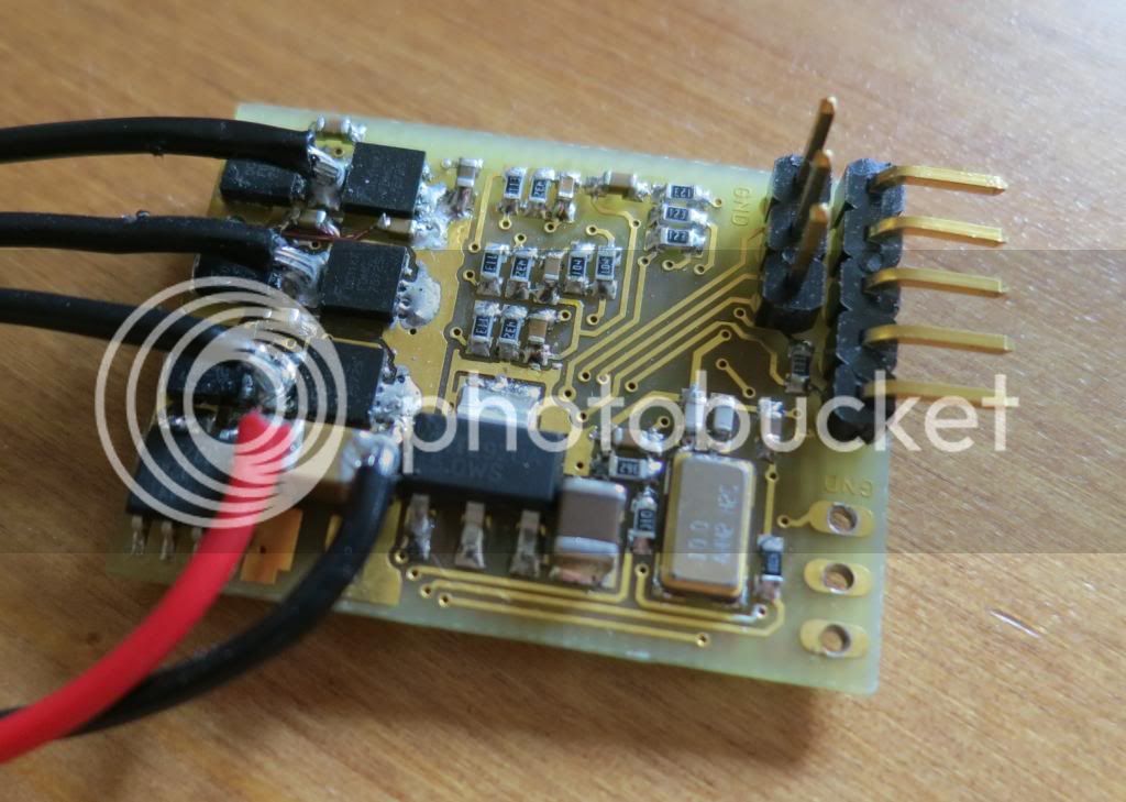
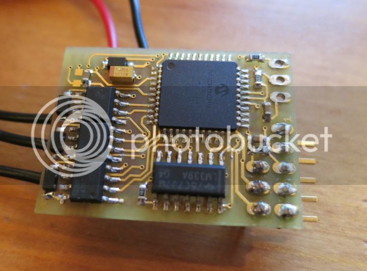
i did try this chip and yes, it significantly reduces commutation noise. i am wondering how to implement this on a sensored controller such as mine. probably just a manipulation of the commutation table. :?:
That makes sense, the trapezoidal method is the same as the space vector modulation but using only 6 steps and alternating null vectors, so some overlapping with PWM adjustment will help transitioning from one step to the other. Increasing overlapping will eventually converge toward full modulation.
I don't think manipulating the commutation table will be enough as you will also need the adjust the PWM during the overlap periods...
 
This topic is great and inspires me to build a bldc controller - if I manage to get some hub motors for my DIY Segway. I'm just wondering - is safe not to isolate the CPU power/ground from the main motor power? I built a H-bridge brushed motor controller and found that it works without isolation at 12volts. However, at 24v and high load (stalled) the CPU goes nuts. I only managed to get it to work by having a separate power supply for the CPU and using optoisolators between its signal and the FET drivers. Would huge capacitors like the 2x4700uf used here prevent the problem I was getting? I only used 100uf.
 
ovaltine said:
This topic is great and inspires me to build a bldc controller - if I manage to get some hub motors for my DIY Segway. I'm just wondering - is safe not to isolate the CPU power/ground from the main motor power? I built a H-bridge brushed motor controller and found that it works without isolation at 12volts. However, at 24v and high load (stalled) the CPU goes nuts. I only managed to get it to work by having a separate power supply for the CPU and using optoisolators between its signal and the FET drivers. Would huge capacitors like the 2x4700uf used here prevent the problem I was getting? I only used 100uf.

It works for me at up to 28V and up to 160A. I use careful ground routing to avoid loop and separated power and logic current path. I had one problem with the 47uf at the input of the DC/DC for the logic that I fixed by adding a diode to avoid the high ripple caused by the power stage capacitors.
 
You are right - careful routing could have fixed my problem. I was using a proto board with built-in ground and power signals snaking throughout the board. I'll have to build a custom PCB and separate the power section like you did. Full respect for your work!

BTW, do you have any spare boards and components that I can buy off you? Those SMDs are hard to get in small quantities.
 
I just looked at the blmc_41 schematics.
The BEMF Comparators are referenced to ground and not to "starpoint". Therefore there is an offset at the zero-crossing detection which causes wrong timing.

"Starpoint" is usually generated by 3 equal resistors connected to each phase.
 
Here is the latest addition to the family: the micro BLDC controller

This controller was optimized to be as light as possible for a solar RC plan project while maintaining the same architecture and SW than my open controller. I only changed a few lines of code to get it going the 1st time.
It weights 3.8gr, measures 32x24mm and can handle 10A phase current from 5.5V up to 15V input voltage. It makes use of 6 power MOSFET in 3x3mm package which turned out to be less difficult to solder than anticipated. Due to their size, they heat up very quickly and reflow in place using a normal soldering iron, the only complication is they need to be kept in place because they are also very light...
As with my other controllers, the throttle commands the phase current/motor torque and benefit from sensorless positioning which allows reliable and high torque startups. This isn't strictly necessary when direct driving a propeller but gives super fast and reliable startups which is nice to have.


IMG_3295_zpsd2b91eee.jpg
 
walls99 said:
Here is the latest addition to the family: the micro BLDC controller
Great! I wish you can share the source files on https://github.com/ , you know, Github is nowadays the home for OpenSource projects.
 
great work walls99
it works good and looks good too :)

you mensioned several times in your post something about the latest version of the code , can you send to me or just publish it , even if it is not ready , i am intersted in the current sense and sync with PWM + PI control OF TORQUE

regards
 
Hi walls99,

Great to see someone using Microchip PIC's rather than the Atmels for this sort of stuff.. Well done!

Are you able to post or PM the current version?

Regards,
Mark
 
Whatever the processor is, I thought the best architecture is a dual CPU circuit: one is purely dedicated to the motion control and the other is for supply voltage, temperature, throttle voltage measurement, external communication and some safety stuff. It is mainly because the time base for the motion control is the PWM period (phase current/voltage sensor ADCs and control loop), and the other things are not required to process in every PWM cycle and basically there is not enough time for them unless a few tricks are applied. Even if it is a multi-100MHz CPU, the ADC has limitations. Longer sampling is better because then the noise is less, but when there are many analog signals in a single CPU then sampling time must be shorter. Furthermore executing an ADC ISR several times in a PWM cycle, putting the samples here and there and executing different filtering on the waveforms has some processing overhead. These can be avoided with a dual CPU design. Another advantage is that it likely allows to get rid of ASM coding. I guess it would be especially useful for sine wave controllers.
Generally my opinion is that the functionally separate processes should be separated in hardware also instead of multitasking in a single CPU.
 
I see what you mean, but someone may think you suggest that only less skilled developers make multi-CPU designs. However the opposite is true ;)
 
When cost considerations are the driving force, reducing the CPU count may be desirable. Multi CPU designs introduce new problems into the mix. I like them, but we often could not afford the extra hardware and had to do the hard realtime programming.

But for an open design it makes a lot of sense (and I have recommended it) as the hard realtime can generally be confined to one processor, and the hacking can be in another, much less critical CPU.
 
Back
Top