Open Sensorless BLDC controller

casainho said:
Walls99, what are the capacitors value you use at input of your controller??

I found that the problem I had were the "ringing" on commutation. I changed the resistors from 10R to 100R and got a better system but I ended up to change again to 470R. No I have no problem but rise/fall time is really bad, about 1us!
I wounder is there is a way to get quick rise/fall times but still avoid the ringing problem.
There is many tricks. The system using irfd9110 and irfd110 fets in a buffer stage I use is one of them. One of the biggest tips I can give is keep all traces dealing with feeding power to and from the fet gates as short as possible. Another is I use a diode across one gate resistor followed by another resistor so I have 33ohms on resistance and 3.4 ohms off resistance. You can also find ferrite beads to fit on the gate leg but make sure you measure the ringing and then find a bead with a spec sheet that has a resistance that is higher at that frequency.

Last but one of the most common tricks is RC snubbers. You can read my powerstage thread and lebowski's IC thread for info on them. As for the use they are a band aid fix they are a fix but at the cost of efficiency and if you design it right you wont need them in the first place. But for guys like lebowski this means a whole new design from scratch! I am going to try to design and redesign to make sure I don't need them. So far ringing is not my problem although I thought it was at 12v but once I upped the voltage it went away.
 
Arlo1 said:
casainho said:
Walls99, what are the capacitors value you use at input of your controller??

I found that the problem I had were the "ringing" on commutation. I changed the resistors from 10R to 100R and got a better system but I ended up to change again to 470R. No I have no problem but rise/fall time is really bad, about 1us!
I wounder is there is a way to get quick rise/fall times but still avoid the ringing problem.
There is many tricks. The system using irfd9110 and irfd110 fets in a buffer stage I use is one of them. One of the biggest tips I can give is keep all traces dealing with feeding power to and from the fet gates as short as possible. Another is I use a diode across one gate resistor followed by another resistor so I have 33ohms on resistance and 3.4 ohms off resistance. You can also find ferrite beads to fit on the gate leg but make sure you measure the ringing and then find a bead with a spec sheet that has a resistance that is higher at that frequency.

Last but one of the most common tricks is RC snubbers. You can read my powerstage thread and lebowski's IC thread for info on them. As for the use they are a band aid fix they are a fix but at the cost of efficiency and if you design it right you wont need them in the first place. But for guys like lebowski this means a whole new design from scratch! I am going to try to design and redesign to make sure I don't need them. So far ringing is not my problem although I thought it was at 12v but once I upped the voltage it went away.
Thank you. I am mainly following my controller, this one from Walls99 and yours Arlo1 -- maybe we can merge them later and create something like what Arduino is for dev boards.
 
Arlo1 said:
Last but one of the most common tricks is RC snubbers. You can read my powerstage thread and lebowski's IC thread for info on them. As for the use they are a band aid fix they are a fix but at the cost of efficiency and if you design it right you wont need them in the first place. But for guys like lebowski this means a whole new design from scratch! I am going to try to design and redesign to make sure I don't need them. So far ringing is not my problem although I thought it was at 12v but once I upped the voltage it went away.

The bolded part isn't entirely true.

Snubbers will prevent body diode conduction*, therefore eliminating these losses. They are normally nearly the same as the switching losses. I measured fet losses dropping ~20% when adding snubbers.

*Given that you run a 'synchronous rectification' algorithm, allways keeping one of the fets on.

Secondly, you can design as correcly as you want - you will have ringing unless you use some exotic fets that employs means to reduce ringing (Most do, actually). Faster switching will give less switching losses.

Note that you can make snubbers virtually lossless, skipping the R and instead having a small SMPS in its place that feeds charge back to the rail. For a three-phase bridge - you can get away with only one such SMPS.

The underlined part is because Coss varies with voltage, something that's been a central topic of all snubber discussions.

I sincerely hope 2013 will be the year that I start building controllers for ebikes, (and possibly a 'clone' of the CA with it xD)
 
Teh Stork said:
The bolded part isn't entirely true.

Snubbers will prevent body diode conduction*, therefore eliminating these losses. They are normally nearly the same as the switching losses. I measured fet losses dropping ~20% when adding snubbers.
I don't agree. Once your snubber cap is charged it should not be flowing current. You might have mesured a reduction in losses in the fets but could that be simply because when it was ringing it was smending more time in the transconductance zone?
 
Arlo, look up "body diode conduction reverse recovery losses" on google and look through the results. These are the losses I eliminated by using a dV/dT limiting snubber.
 
casainho said:
Walls99, what are the capacitors value you use at input of your controller??
I found that the problem I had were the "ringing" on commutation.
You need to add ceramic capacitors to your power capacitors, I used 4x 10uF ceramics in parallel with the 2x 10mF Al cap. The main root cause of ringing is the stray inductance, so in your final layout try to reduce the size of the loop made of the power capacitor, FET, current sensor to minimize Lstray. On my controller, I didn't need gate resistor or snubber to keep the ringing under control thanks to low L stray, low dead time and limited gate current driver (1.8A).

For more info about FET switching, I recommend you read this articles: http://www.eetimes.com/electronics-news/4164421/Estimating-MOSFET-switching-losses-means-higher-performance-buck-converters
 
walls99 said:
casainho said:
Walls99, what are the capacitors value you use at input of your controller??
I found that the problem I had were the "ringing" on commutation.
You need to add ceramic capacitors to your power capacitors, I used 4x 10uF ceramics in parallel with the 2x 10mF Al cap. The main root cause of ringing is the stray inductance, so in your final layout try to reduce the size of the loop made of the power capacitor, FET, current sensor to minimize Lstray. On my controller, I didn't need gate resistor or snubber to keep the ringing under control thanks to low L stray, low dead time and limited gate current driver (1.8A).
Thanks for all the info. The capacitors are VERY expensive!! This is a very expensive controller!!

Low dead time? is that fast as possible switch from one stage to another??

"limited gate current driver (1.8A)" is this some parameter of the mosfet driver?

I now make the max current control differently from what you do (I believe). I do not use a filter on current sensor signal (as before) but now I measure with ADC synchronized to PWM cycle. Now my current control works almost 100% (sometimes I see a cycle out of control). To implement this, I looked at the datasheet of the "old" LPC2103 to found that it can make an interrupt after start or end of duty_cycle. It also have 6 PWM outputs but I am not sure if it can do complementary PWM for synchronous rectification.

Channel 1: 2 ADC reads and compare with max current. Channel 2: PWM signal.
View attachment NewFile76.bmp
Channel 1: 2 ADC reads and compare with max current. Channel 2: current signal (ACS756-50A; 40mV for amp).
View attachment NewFile77.bmp
View attachment NewFile78.bmp
 
casainho said:
The capacitors are VERY expensive!! This is a very expensive controller!!
Farnell has EPCOS 35V, 10000UF for 1.61£ at the moment. There are protecting the 6 FETs at 4£> each and I haven't damaged any FET during development or stress testing in real condition, so I think there are a good investment. Feel free to experiment with lower cost capacitor.

casainho said:
Low dead time? is that fast as possible switch from one stage to another??
That's the time between activating/de-activating the top and bottom FET, I use 300ns.

casainho said:
"limited gate current driver (1.8A)" is this some parameter of the mosfet driver?
yes
 
walls99, could you please describe how do you measure the current and actuate?

Maybe you are doing a different approach... and I would like to learn. Thank you.
 
walls99 said:
casainho said:
walls99, could you please describe how do you measure the current and actuate?

Maybe you are doing a different approach... and I would like to learn. Thank you.
http://endless-sphere.com/forums/viewtopic.php?f=30&t=36479#p528672
Thanks.

So you measure the phase max current only?

What if you are trying to control max of say 10A and you measure 20A?
 
He measures battery current only, it's well documented in the thread.
 
casainho said:
So you measure the phase max current only?
Correct, it is sampled at the end of the ON duty cycle in order to give the current sensor maximum time to stabilize. This gives the max phase current of the PWM cycle but the difference with the min is quite small.
 
Teh Stork said:
He measures battery current only, it's well documented in the thread.
I do actually measure the phase current but using only one current sensor placed just before the power capacitors. This limits measuring the current during ON time of the PWM cycle but is sufficient for the 6 steps method to allow currrent/torque control with a simple PI control loop. This setup also permits cycle per cycle over current protection with about 50us response time worst case scenario and I'm sure has save me quite a few FETs.
 
walls99 said:
I do actually measure the phase current but using only one current sensor placed just before the power capacitors. This limits measuring the current during ON time of the PWM cycle but is sufficient for the 6 steps method to allow currrent/torque control with a simple PI control loop. This setup also permits cycle per cycle over current protection with about 50us response time worst case scenario and I'm sure has save me quite a few FETs.
Assuming your PWM period is such that the current through the motor's phase cannot change by a significant amount, right? Because if it can, you'll not be saved by measuring current only at the end of the PWM ON time.
 
Njay said:
Assuming your PWM period is such that the current through the motor's phase cannot change by a significant amount, right? Because if it can, you'll not be saved by measuring current only at the end of the PWM ON time.
The delta current is about dI=(Vin-Vemf)*dt/L. My worse case scenario: stalled motor, max battery voltage 30V, min inductance 50uH, 100% PWM give an increase of 30A, so that no problem to handle. In fact my software wait for several consecutive over current event to do something about it to avoid false positives. The FETs won't blow up because of a short current pulse (the IRLP3034 that I'm using is actually given for 1308A Pulsed Drain Current) but by the sustained high current that will push the FET into thermal meltdown.
 
walls99 said:
Njay said:
Assuming your PWM period is such that the current through the motor's phase cannot change by a significant amount, right? Because if it can, you'll not be saved by measuring current only at the end of the PWM ON time.
The delta current is about dI=(Vin-Vemf)*dt/L. My worse case scenario: stalled motor, max battery voltage 30V, min inductance 50uH, 100% PWM give an increase of 30A, so that no problem to handle. In fact my software wait for several consecutive over current event to do something about it to avoid false positives. The FETs won't blow up because of a short current pulse (the IRLP3034 that I'm using is actually given for 1308A Pulsed Drain Current) but by the sustained high current that will push the FET into thermal meltdown.
Walls99, thank you for the detailed explanation. I am being talking by phone with NJay since he is Portuguese also and is more productive for me to explain and listen in Portuguese :)

You are taking a different approach. I am doing as NJay suggested, using a comparator (but I am using instead an ADC with success, it takes 3us for reading a value) to find on each PWM cycle when the current reaches the maximum value and then disable the "remaining duty_cycle". And I know that to measure the average current I should measure and end of duty_cycle as you do for max current control. My LPC2103 generates an interrupt at start/end of each cycle and at end of duty_cycle, very nice for this application :) I am now more aware of the resources needed for this controller! - is a pleasure for me to learn :)
 
walls99 said:
Good and bad day today, I have being able to confirm that with 160A phase current, repetitive acceleration and regen braking, I can warm-up my controller and trigger the temperature alarm currently set at a lowish 50C. Doubling the phase current also allowed me to confirm that my controller can handle 3KW peak.
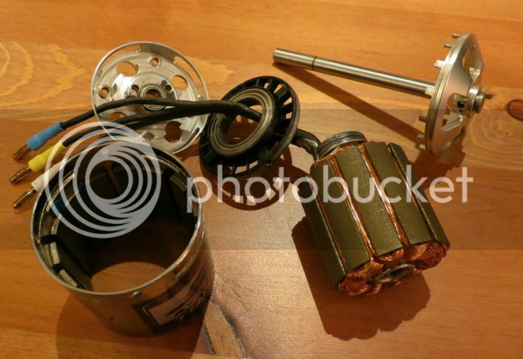
Unfortunately the SK3 6374 motor didn't like that treatment too much and got quickly hot even with the sizeable radiator. More worryingly there is now something loose in the motor, so I'll have to take it out to find out more about the damage...
Turned out to be a few screws that went loose, it's now all back together and running smoothly. Here is a picture of the motor before re-assembly:
IMG_1681_zpsc641e76f_s_zpsf0ca7893.jpg


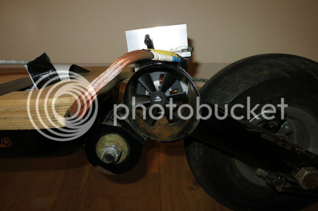
Given the motor gets quite hot with 160A phase current, I have improved the cooling by adding a fan:
IMG_1771_zpsaaad6e0e.jpg
 
Hi Walls,

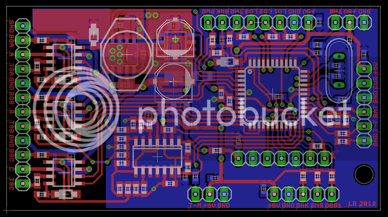
What software are you using four your pic ?

And i also noticed you named the pins on the upper connectors THR LD1 LD2 BRK PWR on your pcb layout.

brain_40.png


Could you explain me what they stand for and to what they are used for.
 
Hi, this is a very interseting thread as i am playing right now to build my own controller too.
With your source code and all the details it just gives me more enthusiasm to continue my project.

If you dont mind, I would like to know what parameters did you looked at to choose the regulator on your design (max5035) and the cap values on the bootstrap of the driver (1u).
Also, what is the chip just above the 12v regulator, there is no p/n on it or no labels. An alternate regulator ?

Thanks VERY much for this thread and the open source !! :eek: :eek:
 
patallen said:
If you dont mind, I would like to know what parameters did you looked at to choose the regulator on your design (max5035) and the cap values on the bootstrap of the driver (1u).
Also, what is the chip just above the 12v regulator, there is no p/n on it or no labels. An alternate regulator ?
Hi patallen.

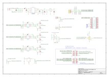
I am doing my controller and the schematic is based on this one from Walls99 - I can say that it works very well for me. I am sharing here the schematic and pictures/videos and I hope it can help you and answer to your questions. Here is the current schematic (prototype 3):
EBike_Smart_Controller-prototype_3.jpg
And here pictures and videos (prototype 3):
[youtube]I449L6JZkV0[/youtube]

[youtube]wrrfMGUwaAM[/youtube]

[youtube]M8jWLfEaA3E[/youtube]


patallen said:
If you dont mind, I would like to know what parameters did you looked at to choose the regulator on your design (max5035) and the cap values on the bootstrap of the driver (1u).
I chose the max5035 for its wide input voltage range and low shutdown current. For the bootstrap, the recommendation is a few 100nF and 1u was the closest value available to me.

patallen said:
Also, what is the chip just above the 12v regulator, there is no p/n on it or no labels. An alternate regulator ?
It's a 5V LDO in SOT223 format for the 2nd 5V power rail from the 12V switcher which is switched off in standby mode. The other 5V LDO (LM9076) is for the PIC only and is always on.
 
thanks guys for the reply.

i found some bugs in my code that may explain why my proto P3 went south. will work that out and be more carefull on my next test.

I used the ir2181 on my P1 and P2 and i toasted few for no obvious reasons.... :?: i went with the IR2136.

thanks for the details, i like this forum very much.
 
patallen said:
thanks guys for the reply.

i found some bugs in my code that may explain why my proto P3 went south. will work that out and be more carefull on my next test.
So is your OpenSource your project? If so, please share the link as I would like to see/learn with it.
 
Back
Top