
You are using an out of date browser. It may not display this or other websites correctly.
You should upgrade or use an alternative browser.
You should upgrade or use an alternative browser.
Open Sensorless BLDC controller
- Thread starter walls99
- Start date
casainho
10 GW
- Joined
- Feb 14, 2011
- Messages
- 6,047
Ok, thank you. I will keep reading your work that you share here. Thanks for sharing.walls99 said:Hi Casainho,
I'm afraid you are a bottom of a steep learning curve and I don't really have time to help you with the basic principle of sensorless BLDC control, there is a lot literature out there for that. I'll keep an eye on your progress here and help if I can.
Thanks.
casainho
10 GW
- Joined
- Feb 14, 2011
- Messages
- 6,047
I am reading your firmware V1.1 and I want to learn with it. Some years ago I wrote code in assembly for PICs and AVRs, it is nice to read your code and remember those times and also see how you did you resolve the questions about BLDCwalls99 said:bearing said:Is this the latest version of the projekt?
I would like to play with this, and then maybe make a board which can drive a 80100 on 80V.
No, it's quite out of date. I'm planning on releasing new soft but I haven't had the time to finalize everything I wanted. They are many upgrade to handle "high power": Torque control, automatic advance timing, sensorless startup, temperature control, regenerative braking...
I've sent you a PM to discuss alpha release, if you're interested?
")
Thank you for sharing the source file with the comments. Please fully comment your new code, if possible. Thank you.
My current notes to your firmware/system:
- Timer1 is used for measure throttle impulse time; CCP1 is used to detect start and stop of throttle impulse.
- Battery/system low voltage detection resets the system.
casainho
10 GW
- Joined
- Feb 14, 2011
- Messages
- 6,047
Hello Laurent.
Could you please tell me what is:
1 - the meaning of AUTO_STEP and STEPPING_ON flags on BMC_STATUS variable? When they are 1, what system is supposed to do?
2- Windmill strategy for start-up you mention on the code is the same as you explained here? http://endless-sphere.com/forums/viewtopic.php?f=30&t=36479&start=15#p534016
Thank you.
casainho said:Hello Laurent.
Could you please tell me what is:
1 - the meaning of AUTO_STEP and STEPPING_ON flags on BMC_STATUS variable? When they are 1, what system is supposed to do?
2- Windmill strategy for start-up you mention on the code is the same as you explained here? http://endless-sphere.com/forums/viewtopic.php?f=30&t=36479&start=15#p534016
Thank you.
The "Windmill" strategy start-up relies one the motor already rotating and simply waiting for a few ZC to synchronize the timing loop. This requires the user to push the motor/vehicle to start.
The start-up by position/current sensing is an active way to start the motor by exciting the motor as if hall sensor where used.
STEPPING_ON enable/disable stepping. Stepping need to be off during windmill start-up
AUTO_STEP is a flag that indicates the next step is updated automatically based on the timing of the BEMF zero crossing.
casainho
10 GW
- Joined
- Feb 14, 2011
- Messages
- 6,047
Ok, thanks.walls99 said:The "Windmill" strategy start-up relies one the motor already rotating and simply waiting for a few ZC to synchronize the timing loop. This requires the user to push the motor/vehicle to start.
This is not implemented on the latest firmware V1.1 you shared, right?walls99 said:The start-up by position/current sensing is an active way to start the motor by exciting the motor as if hall sensor where used.
I need to read more and learn about the need of demagnetization... Could you please explain the ADV_TABLE -- "Calculate the advance value using a table (hardware dependant)"??
casainho
10 GW
- Joined
- Feb 14, 2011
- Messages
- 6,047
Hello Laurent.
I am looking at the schematic components values, as I am trying to understand it better and make a BOM. I am thinking if I can invest on this board/project and use it to control my electric bicycle of 48V and motor of 500W (but for start I will test with my old system of 24V and 250W motor). Do you know if this board/system is able to control my motor of 48V (Q100 350W motor)??
If I invest, I will need to do it also for buying a PICKit2 for programming and debug the firmware, as I will want to make the firmware in C and not assembly as you did. I will develop on Linux. I will also add the Bluetooth module to UART RX and TX lines.
How did you produced your PCBs? Do you have experience with a service for PCBs? Can you recommend a service for PCBs?
casainho said:Hello Laurent.
I am looking at the schematic components values, as I am trying to understand it better and make a BOM. I am thinking if I can invest on this board/project and use it to control my electric bicycle of 48V and motor of 500W (but for start I will test with my old system of 24V and 250W motor). Do you know if this board/system is able to control my motor of 48V (Q100 350W motor)??
If I invest, I will need to do it also for buying a PICKit2 for programming and debug the firmware, as I will want to make the firmware in C and not assembly as you did. I will develop on Linux. I will also add the Bluetooth module to UART RX and TX lines.
How did you produced your PCBs? Do you have experience with a service for PCBs? Can you recommend a service for PCBs?
You will have to make a few software and hardware adjustment to run my design at 48V. It's currently set up for 30V and use IRLP3034 instead of IRFP4368. However this e-bike hub motor is not really difficult to drive and can't handle 100A, so you are probably better off using an simple e-bike controller...
For my PCB, I use PCB-POOL.
casainho
10 GW
- Joined
- Feb 14, 2011
- Messages
- 6,047
Thank you. I were reading your assembly code and I did understand a few more things, but is hard. I changed my ideas and for now I will go with hall sensors, is much more easy and will also let me understand better how all this work/should work.walls99 said:You will have to make a few software and hardware adjustment to run my design at 48V. It's currently set up for 30V and use IRLP3034 instead of IRFP4368. However this e-bike hub motor is not really difficult to drive and can't handle 100A, so you are probably better off using an simple e-bike controller...
For my PCB, I use PCB-POOL.
I have now the schematic and firmware almost done (in C). Here some pictures of my working prof of concept (KU63 controller adapted to be controlled from external microncontroller LPC2103):
As you can see, I am using the same current sensor (ACS756 50A) as you do - thanks for sharing!
Before adding the current sensor (ACS756 50A):
casainho
10 GW
- Joined
- Feb 14, 2011
- Messages
- 6,047
walls99 said:I was also planning to use position sensor to have full start-up torque but I found that position sensing by current measurement works very well with this type of motor. The permeance varies significantly from one electric position to the other and the permeance is minimum for the electrical position that is aligned with the mechanical position. Also with this type of low inductance motor, the 6 positions scanning is fast enough not to reduce the starting torque (~500us in my case). This approach gives me ~90% of the full potential star-up torque at 5ms sampling rate and it's good for speed up to 100RPM where the BEMF is strong enough to detect Zero Crossing...barryfzr said:I had decided to go down the sensor route though with an Austria Micro Systems As5040(or lower spec 8bit output) which can provide the commutation signals direct.
See below the position sensing cycle, the current is maximum when the permeance is lowest:
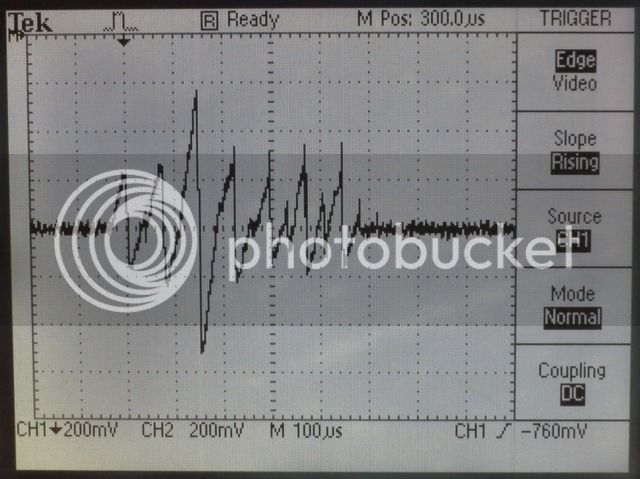
Last time I wanted to go with Hall sensors and avoid BEMF since it is difficult to start with. But quickly one Hall sensor of my motor stoped to work -- maybe I made some short circuit with it. I am now back to BEMF and I were able to reproduce your results.
On my motor Cute 85, 24V, 250W, I can energize it by 100us and found the position of rotor/sector. Interesting is that my results are a bit different from yours, because energizing 100us I only get current on 2 sectors (one getting more current than the other). Using like 500us I will get current in all sectors however the current on the 2 aligend/"strong" sectors will be to much high!
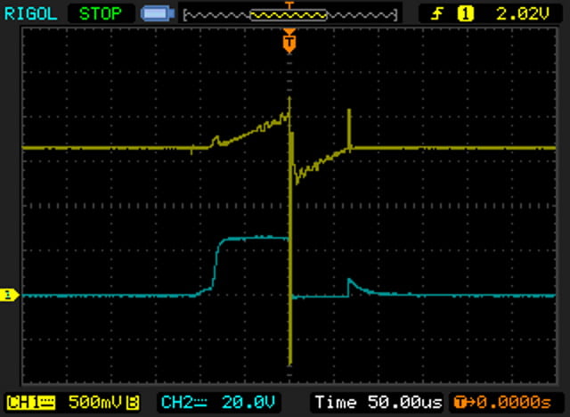
Here is a screenshot of my scope:
Yellow: current signal
Blue: mosfet gate voltage
Attachments
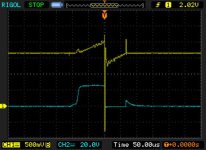
On my motor Cute 85, 24V, 250W, I can energize it by 100us and found the position of rotor/sector. Interesting is that my results are a bit different from yours, because energizing 100us I only get current on 2 sectors (one getting more current than the other). Using like 500us I will get current in all sectors however the current on the 2 aligend/"strong" sectors will be to much high!
Do you need to get current in all sectors? isn't it enough to get high current in one sector?
Do you have a 25V gate drive?
Thats a great picture its neet to see the inductance slowly letting the amps climb. What is the strait up and down spike on the current that is lined up with a small spike on the gate after the on and off time??casainho said:walls99 said:Here is a screenshot of my scope:
Yellow: current signal
Blue: mosfet gate voltage
casainho
10 GW
- Joined
- Feb 14, 2011
- Messages
- 6,047
I am learning here... but seems that I can identify the correct sector by measuring the highest current. If it will work, I will be more than happybearing said:Do you need to get current in all sectors? isn't it enough to get high current in one sector?
-- my target is to start the motor without having the BEMF circuit working.I don't know. I am using KU63 controller and external board with microcontroller. See here the schemarics:bearing said:Do you have a 25V gate drive?
- KU63 schematic: http://www.avdweb.nl/Article_files/Solarbike/Motor-controller/China-BLDC-motor-controller-36V-250W.pdf
- EBike Smart Controller schematic: http://endless-sphere.com/forums/download/file.php?id=94917&mode=view
casainho
10 GW
- Joined
- Feb 14, 2011
- Messages
- 6,047
I don't know but I used this code:Arlo1 said:What is the strait up and down spike on the current that is lined up with a small spike on the gate after the on and off time??
Code:
  while (1)
  {
    commutation_sector (1);
    delay_us (100);
    commutation_disable ();

    for (i = 0; i < 50; i++)
    {
      delay_us (100);
    }
}Arlo1 said:Thats a great picture its neet to see the inductance slowly letting the amps climb. What is the strait up and down spike on the current that is lined up with a small spike on the gate after the on and off time??
Probably noise. When the current switches direction, it will induce a spike across across the ground. The sensor GND is probably not connected at the same point as the scope ground.
casainho said:I don't know. I am using KU63 controller and external board with microcontroller. See here the schemarics
In those schematics, the gate drive is 14V, but on your scope they are about 25V. Many MOSFETs have a max gate voltage of +-20V.
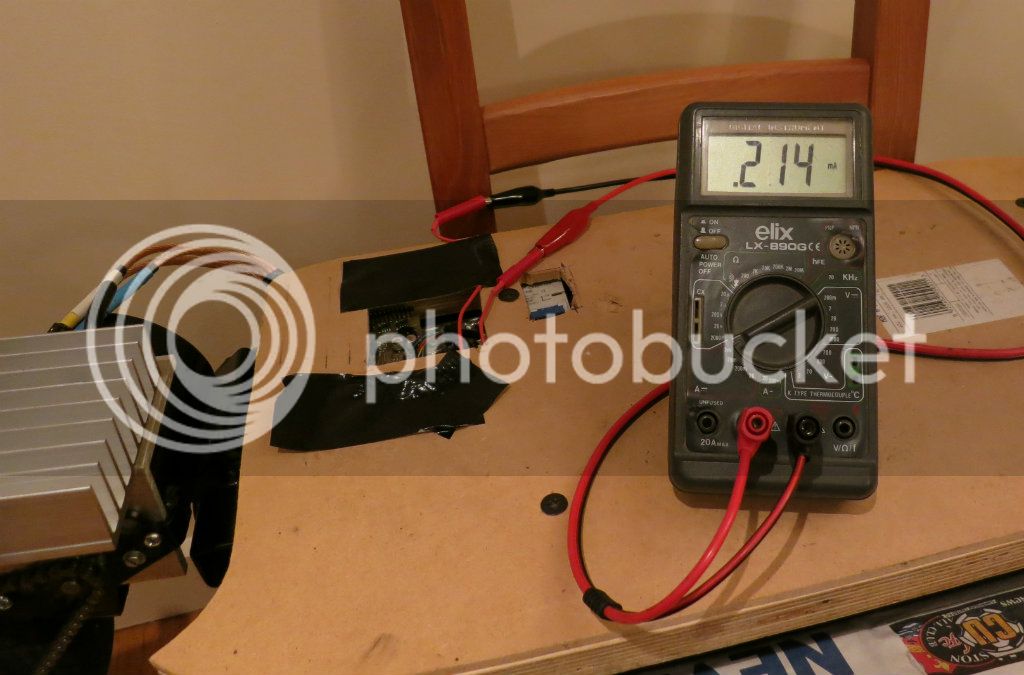
Since the Goped is not quite amphibious, I had a some time to work on the controller over the past few weeks and focused on power management. 1st, it can now work with my BMS to cut off the power when any of the cell reach LVC level and disable the motor when plugged in for charging. 2nd, I've optimized the standby power of the controller down to 215uA, most of this is the input capacitor leakage now. With the 140uA of the BMS, it will take about 5years to empty my battery, so I should be ok
This is how it looks inside now:
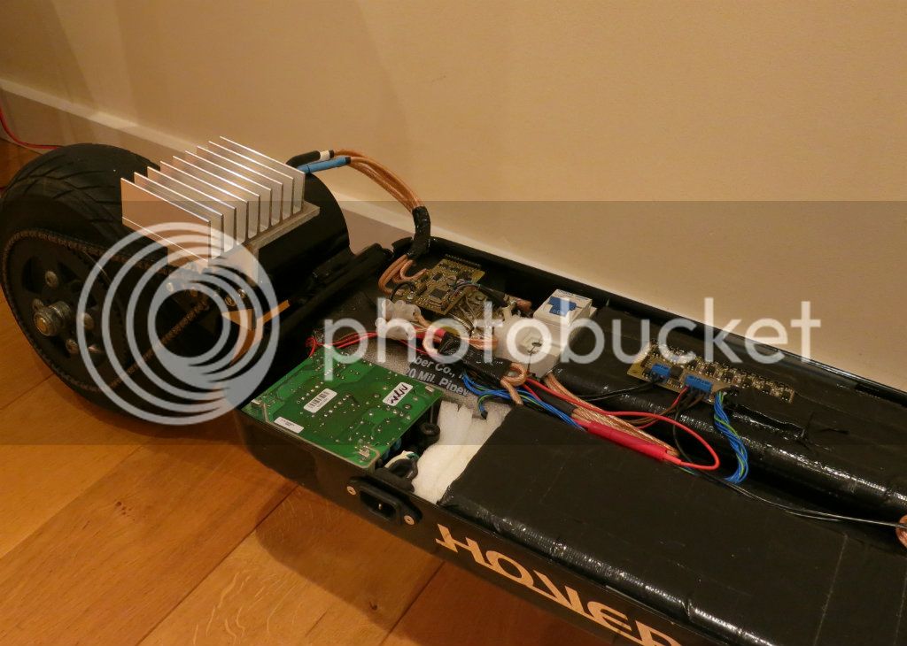
This is how it looks inside now:
casainho
10 GW
- Joined
- Feb 14, 2011
- Messages
- 6,047
Hello Walls99.
Finally I got my motor working (using hall sensors) including the throttle (but my motor still doesn't always start). All code in C
[youtube]mfAeUDZ1xsE[/youtube]
Soon I want to design a board and I hope to use your hardware/schematic but removing the BEMF circuit and add the hall sensor circuit. I may even go with the same PIC.
And I setup a page for documentation, including git for hardware/firmware/software: http://smartebike.sourceforge.net/
casainho
10 GW
- Joined
- Feb 14, 2011
- Messages
- 6,047
Hello walls99.
I found that my current prototype can't be drived correctly (the KU63 mosfet circuits) with the 3.3V from the microcontroller I am using. I decided to build a new power stage that works correctly with the 3.3V and I will build your schematic, mainly the power supply stages of +12V and +5V, the mosfets + drivers, the current sensor (that I am already using on current prototype) and finally the temperature sensor.
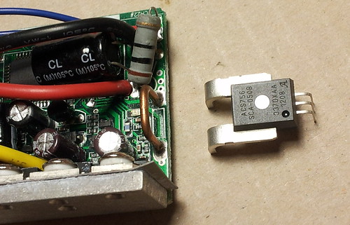
I have one question: can you please tell me what kind of power switch for protecting over current are you using? Like on this image you shared before:
I found that my current prototype can't be drived correctly (the KU63 mosfet circuits) with the 3.3V from the microcontroller I am using. I decided to build a new power stage that works correctly with the 3.3V and I will build your schematic, mainly the power supply stages of +12V and +5V, the mosfets + drivers, the current sensor (that I am already using on current prototype) and finally the temperature sensor.
I have one question: can you please tell me what kind of power switch for protecting over current are you using? Like on this image you shared before:
casainho said:I have one question: can you please tell me what kind of power switch for protecting over current are you using? Like on this image you shared before:
It's a 100A MCB that I got from ebay here.
I found a problem with my controller: I can't get it to warm-up. The main reason is that I'm not pushing enough current through it with a max phase current of 80A. Luckily, the solution was simple: replace the 100A current sensor by a 200A one!
I had a quick test with the new sensor, ACS758ECB-200B, the motor unloaded, a max phase current of 160A and it seemed to work. Next I will do more load testing and work out how to adjust the current dynamically to avoid burning the motor.
In the mean time I took a few pictures of the power stage while it was out:
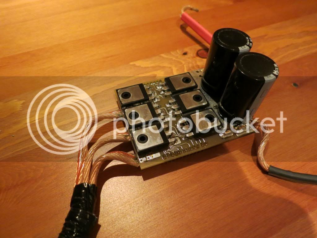
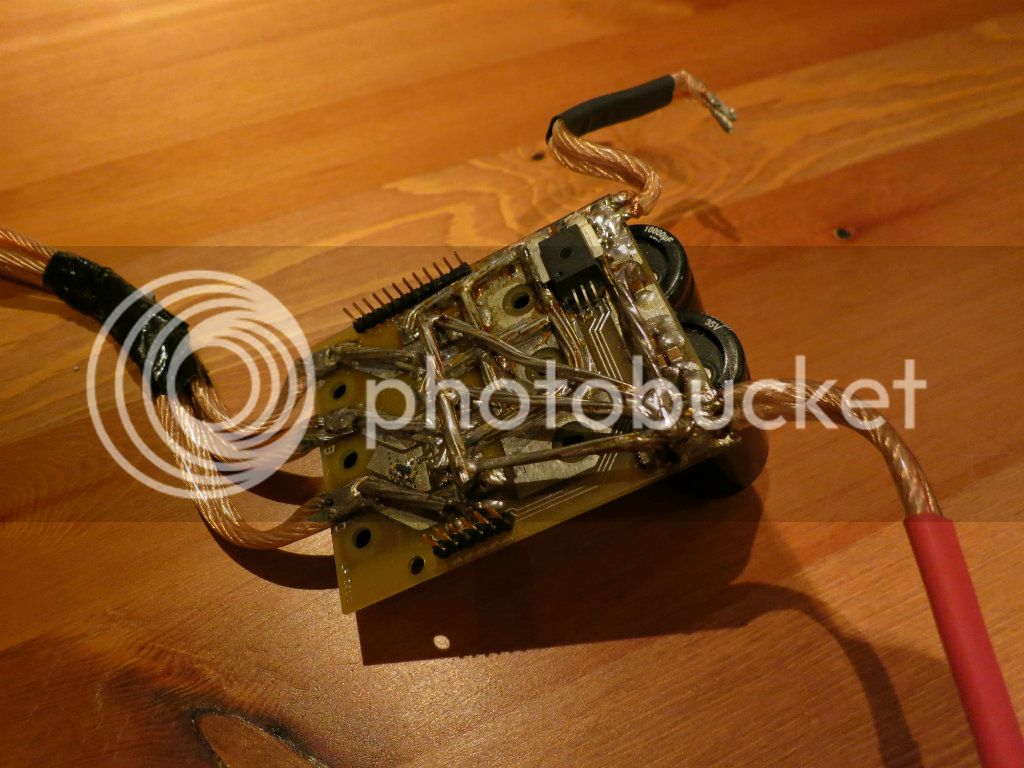
casainho
10 GW
- Joined
- Feb 14, 2011
- Messages
- 6,047
Great! I was just asking you about the way you put the heatsink on the mosfets. That way, is the LM50 temperature sensor working? Seems to me that is far and not in contact with the heatsink and the mosfets...walls99 said:In the mean time I took a few pictures of the power stage while it was out:
Did you saw already the 100A MCB working? During the development, how did you protected against short circuits/over current?
I am now working with a 30V 10A lab power supply but soon I will install my prototype on the bicycle and I will need to protect against the short circuits/over current.
By the way, I bought cheaper mosfests (I hope they will work ok): MOSFET,N CH,80V,100A,TO-220AB, NXP - PSMN6R5-80PS, Farnell #1845669.
My design has good heat conduction (lot of coper re-enforcement) and a large enough thermal mass that the temperature sensor doesn't need to be on the heat sink, the entire controller heats up and the LM50 picks this up with just a little big of lag.casainho said:That way, is the LM50 temperature sensor working? Seems to me that is far and not in contact with the heatsink and the mosfets...
Thankfully not! I used a lab power supply during the development, now it's stable enough that the on-board OC software handles the shorts. The MCB is more to protect for shorts before the controller which could cause the scooter to burn up. My pack is made of 7x A123 batteries in parallel to have enough capacity but that means a pulse discharge of 840A, I've already "vaporised" connectors because of that...casainho said:Did you saw already the 100A MCB working? During the development, how did you protected against short circuits/over current?
casainho
10 GW
- Joined
- Feb 14, 2011
- Messages
- 6,047
I would like to know what voltage are you working with. I can't understand the voltage and amps of your battery. And can you please tell me what voltage and current does your lab power supply do?walls99 said:Thankfully not! I used a lab power supply during the development, now it's stable enough that the on-board OC software handles the shorts. The MCB is more to protect for shorts before the controller which could cause the scooter to burn up. My pack is made of 7x A123 batteries in parallel to have enough capacity but that means a pulse discharge of 840A, I've already "vaporised" connectors because of that...casainho said:Did you saw already the 100A MCB working? During the development, how did you protected against short circuits/over current?
My lab power supply just do 30V 10A, is ok for a 24V motor but not for my current bicycle of 48V. Although I bought a new cheap bicycle and (another) 24V motor (Cute85/Q85) just for develop/test this controller, later I would like to go for 48V to bicycles and scooters. When you say scooter do you refer to your goped?
Similar threads
- Replies
- 3
- Views
- 623
- Replies
- 11
- Views
- 1,175
- Replies
- 6
- Views
- 818