Open Sensorless BLDC controller

Love your work!

I'm working on a controller with three current sensors, it's mainly since you can't sample current with two current sensors at 100% pwm that I use it (And for running FOC) - but one current sensor and controll like you show seems like a cheap and efficient way of controll. I'm thinking about trying to mate such a motor to a CVT with a slip clutch so that there is no load at bottom of load range. I've got some experience with moped CVT's, but I'm thinking about controlling one with a microcontroller and some PID loops. Some time in the future :)
 
walls99 said:
This is my DIY inertia wheel load on a SK3 6374-192kv, accelerating to 4500RPM with 80A phase current, 1370W peak power, sensorless start-up, sensorless 6 step method and adaptive advance.

Very nice work. It looks like it starts well, and transitions to EMF sensing without a glitch.
 
Oh men, I am trying to do the same but seems I lack a lot of technical information about BLDC motors.

walls99, please see what I did already on EBike Smart Controller: http://endless-sphere.com/forums/viewtopic.php?f=3&t=38337

Thank you for sharing!!
 
Hello walls99.

I were quick reading your assembly code. I would like to ask you:
1. Why did you code in assembly and not in C? C would be easier to understand (at least for me) but I must say your comments on the code are great - thanks.
2. Why aren't you testing your controller with a ebicycle hub motor?

Could you please give a look to the schematic KU63 controller I am using and provide your opinion about it? Could you please tell me what strategy I could use to startup the motor in sensorless (my motor don't have hall sensors).

Thank you for sharing.
 
casainho said:
1. Why did you code in assembly and not in C? C would be easier to understand (at least for me) but I must say your comments on the code are great - thanks.
Sometime I ask myself the same question when I try to re-read my own code :). The practical answer is that C would be better for many good reason but not fast enough on the PIC 18F. Also, I'm doing this project for fun and I like the challenge!

casainho said:
2. Why aren't you testing your controller with a ebicycle hub motor?
I've designed my controller to handle low-ish inductance RC motors in high load condition without burning like most commercially available controller do, to use on my ESR Goped. I don't have a hub motor but I wouldn't expect any surprise.

casainho said:
Could you please give a look to the schematic KU63 controller I am using and provide your opinion about it?
I did, it's very similar in principle to my controller. It's simple and low cost, so definitely a good starting point.

casainho said:
Could you please tell me what strategy I could use to startup the motor in sensorless (my motor don't have hall sensors).
Check above Positioning by current sensing
 
My mistake. Message to delete.
 
casainho, go read up on some application notes. There are dozens out there with sensorless startup routines! Atmel is a great place to start ;)
 
walls99 said:
casainho said:
1. Why did you code in assembly and not in C? C would be easier to understand (at least for me) but I must say your comments on the code are great - thanks.
Sometime I ask myself the same question when I try to re-read my own code :). The practical answer is that C would be better for many good reason but not fast enough on the PIC 18F. Also, I'm doing this project for fun and I like the challenge!
Seems you are using your PIC at 40MHz (10MHz each CPU clock cycle). I am using a cheap ($10) 32 bits ARM7 board running at 48MHz, so, 4.8 times more processing power as your board (or even more since your PIC version is 8 bits).

KU63 controller drived my Cute-85 motor with PWM signal of 15.6KHz. The lowest velocity have a 31.6ms period of each phase commutation. The highest velocity, 2.24ms.
I hope my board at 48MHz will work ok. Even I think my e-bicycle motor have a lower rotation than yours motor.

I really think we need a kind of Arduino on e-bicycle controllers, I mean, an OpenSource and well documented controller. Also with commercial success.

I would like to get help, developers and testers joining my effort.

walls99 said:
casainho said:
Could you please give a look to the schematic KU63 controller I am using and provide your opinion about it?
I did, it's very similar in principle to my controller. It's simple and low cost, so definitely a good starting point.
Good to know that is simple and low cost, that is what we need :) -- it works perfectly on my bicycles.

And the KU63 BEMF circuit seems similar to yours, however KU63 BEMF circuit have a signal (PWM), CPU-34 on the schematic, from the controller that interacts with BEMF circuit. This PWM signal is only used at startup/low speed.

Could you please explain your BEMF circuit, logic behind it? How do you use the output of this circuit in the firmware?

walls99 said:
casainho said:
Could you please tell me what strategy I could use to startup the motor in sensorless (my motor don't have hall sensors).
Check above Positioning by current sensing
Thank you for your explanation! The oscilloscope pictures and your explanation are great - thank you for sharing.

I will energize the motor, using the 6 steps, with 50us each step and look at the current with oscilloscope. I hope to see the same as you. I will report later.
After I will implement your strategy of searching the rotor position and energize the "next" (+120º) phase.

walls99 said:
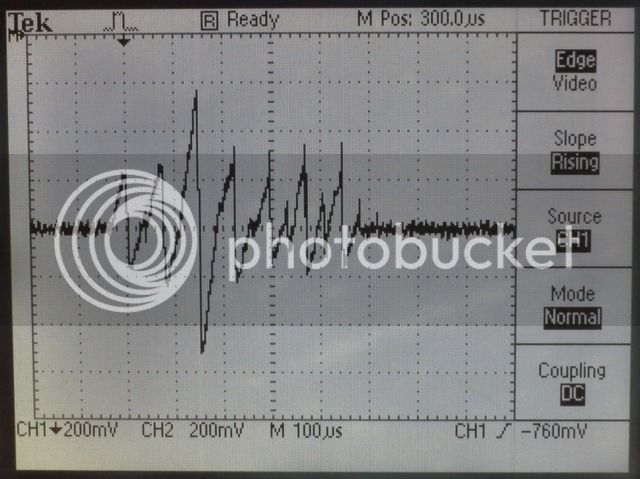
The permeance varies significantly from one electric position to the other and the permeance is minimum for the electrical position that is aligned with the mechanical position. Also with this type of low inductance motor, the 6 positions scanning is fast enough not to reduce the starting torque (~500us in my case). This approach gives me ~90% of the full potential star-up torque at 5ms sampling rate and it's good for speed up to 100RPM where the BEMF is strong enough to detect Zero Crossing...

See below the position sensing cycle, the current is maximum when the permeance is lowest:
IMG_0182.jpg


The principle is simple, I'm using the standard 6 steps of the trapezoidal control for BLDC Motors, energizing each step for a fixed time (~50us in my case) and measuring the current delta for each step. The step with the highest current delta is is the most likley to be aligned with the mechanical position of the rotor. From there, I energize the mechanical position + 2 steps or 120 degrees advance in constant current/torque mode, wait for 5ms and repeat the 6 steps scan + 5ms drive until the motor speed is fast enough to cover the 2 steps advance in less than 5ms. At this point I switch to the BEMF sensing method.
 
casainho said:
I really think we need a kind of Arduino on e-bicycle controllers, I mean, an OpenSource and well documented controller. Also with commercial success.

I don't think this is possible. Once you get to a stage where you're project
is worthwile the big China companies will start producing it leaving you as
a developer out of the loop. Why would they give you money when all they
need is freely available on the internet ?
 
Lebowski said:
casainho said:
I really think we need a kind of Arduino on e-bicycle controllers, I mean, an OpenSource and well documented controller. Also with commercial success.

I don't think this is possible. Once you get to a stage where you're project
is worthwile the big China companies will start producing it leaving you as
a developer out of the loop. Why would they give you money when all they
need is freely available on the internet ?
Maybe you have reason. I don't care about money on this project, I am not working professional on it. I am only a user and a maker, I am trying to develop and implement what I need since no one is selling it. But I think this project would have for sure success with a business plan. If someone produces and sells what I am looking (and developing), I would be happy to buy.

I am already buying and using "chinese" controllers and I am also taking advantage of them to develop my own controller for my needs.

Maybe we can find a project leader and manager, someone who will try to get funding and producing it. Funding on kickstarter or other site like that. There are a few OpenSource gadget shops that produces and sells OpenSource projects from ideas of users: Sparkfun, AdaFruits, Olimex, etc.

Lebowski, can you share with us your plan for your controller?
 
the plans for my controller are to design a PCB (in progress), after that
I want to add rotor position sensing by measuring winding inductances
for powered startup at motor standstill.

board.jpg
 
Lebo, a quick tip FWIW, vertical mount leaded components tend no to be optimum in high vibration and shock environments.
 
Hey Walls. With my controller project I did it all in the open. I didn't licence it as an open source don't know much about that. I will be working on the code more this winter.
I made mine modular so we can make any power level with it we want. I like things in the open. I just want to get my off the ground to encourage more people to build them and to try to help prices come down. I love what I have learnt and cant wait to learn more.

On the other hand lebowski is right he has a skill and put a lot of time into his code so that is worth money to him. I would like to see lebowski sell chips and full controllers to maybe help with his financial need when his job ends in a few months. So I in no way want to hurt his sales if anything I will try to make a few items to help sell kits for him!

SO when I get back to the code this fall I will work on it open source and hopefully get peoples help. If not no biggie But I see a steep learning curve ahead and will likely take 5 years? to get the features lebowski has and will not likely be the same I will write code for different options on my way. As for why I will do this open source? Because I don't know enough to sell my code. IN 5 years maybe but by then I will maybe write code for something else to make money. At the end of the day I just want to go fast! :)
 
Arlo1 said:
Hey Walls. With my controller project I did it all in the open. I didn't licence it as an open source don't know much about that. I will be working on the code more this winter.
Hello Arlo1.

Your thread is big, I can't find now time to read it all. Do you have working firmware? If so, could you please consider to use github to host the project sources?? Github also provides a wiki, which is great for documentation, instead forum messages.

Here is the github for my EBike Smart Controller project: https://github.com/casainho/EBike-Smart-Controller
 
Lebowski said:
bigmoose said:
Lebo, a quick tip FWIW, vertical mount leaded components tend no to be optimum in high vibration and shock environments.

Let's hope for the best then, it'll be the only way in which it's all going to fit....

Unfortunately, hoping for the best is no substitute for doing it right. Even the Chinese realize the problems that those vertical parts can cause. Potting or lots of RTV'd components might help.
 
Lebowski said:
bigmoose said:
Lebo, a quick tip FWIW, vertical mount leaded components tend no to be optimum in high vibration and shock environments.

Let's hope for the best then, it'll be the only way in which it's all going to fit....
I realy think its best to be modular have the brain on one board and the powerstage seprate. Then people are able to build it to suit their needs and replace blown power stage parts with less trouble.
 
Arlo1 said:
Lebowski said:
bigmoose said:
Lebo, a quick tip FWIW, vertical mount leaded components tend no to be optimum in high vibration and shock environments.

Let's hope for the best then, it'll be the only way in which it's all going to fit....
I realy think its best to be modular have the brain on one board and the powerstage seprate. Then people are able to build it to suit their needs and replace blown power stage parts with less trouble.

Modular, that's the next step. First I want to do a 6 FET board which should maybe be capable of around 10 kW with TO247
(when you use 150 V devices, 120 V battery, 120 A phase amplitude (irfb 4568) gives around 80 A batter current -> 10 kW at
a dissipation of 22W per FET, is that do-able?). What kind of heatsink would 132 W of dissipation need ?

Dependent on how things go with the 6 FET I would like to design a 2 FET module including a full bridge, 2 caps, snubbers, current sensor
and a gate driver IC. 3 modules with a brain-board would give you a 6 FET, 6 modules with a brain-board a 12 FET controller etc etc...
 
texaspyro said:
Lebowski said:
bigmoose said:
Lebo, a quick tip FWIW, vertical mount leaded components tend no to be optimum in high vibration and shock environments.

Let's hope for the best then, it'll be the only way in which it's all going to fit....

Unfortunately, hoping for the best is no substitute for doing it right. Even the Chinese realize the problems that those vertical parts can cause. Potting or lots of RTV'd components might help.

Maybe it also depends, I plan to use a double sided board with proper through-metalised via's. I cannot imagine components
breaking out then (single sided without vias, then it is maybe possible)
 
It's not that they break out of the holes. It's that the parts wiggle back and forth, and break their leads off above the PCB. ;)
 
The proto's will work fine either way. If you were to manufacture them and have them used widely in the field, that is when you will see the problem. In the area I work in we must analyze for solder fatigue under vib and shock loads. My comment and advice comes from that experience. Granted, we are talking about environments 6 sigma more severe than an eBike, but the principles hold in general across the board.

... or as others have said to me: "Moose you are ruined for designing consumer products!" :p
 
casainho said:
Could you please explain your BEMF circuit, logic behind it? How do you use the output of this circuit in the firmware?

The BEMF circuit is a standard voltage divider + low pass filter + virtual neutral comparator for Zero Crossing detection feeding the Input Capture module of the PIC. There is a lot of literature available about the Zero Crossing principles. I suggest you read this 2000+ post thread DIY BLDC controller.

The low pass filter is designed to limit the phase lag to below 30º for the maximum RPM, so it can be compensated for by adjusting the phase advance in software. I also make use of the PIC digital noise filters to reduce the interference from the PWM signal.

See attached, the BEMF filter LTspice:
View attachment bemf_filter_3.zip
 
Arlo1 said:
Hey Walls. With my controller project I did it all in the open. I didn't licence it as an open source don't know much about that. I will be working on the code more this winter.
I made mine modular so we can make any power level with it we want. I like things in the open. I just want to get my off the ground to encourage more people to build them and to try to help prices come down. I love what I have learnt and cant wait to learn more.

On the other hand lebowski is right he has a skill and put a lot of time into his code so that is worth money to him. I would like to see lebowski sell chips and full controllers to maybe help with his financial need when his job ends in a few months. So I in no way want to hurt his sales if anything I will try to make a few items to help sell kits for him!

SO when I get back to the code this fall I will work on it open source and hopefully get peoples help. If not no biggie But I see a steep learning curve ahead and will likely take 5 years? to get the features lebowski has and will not likely be the same I will write code for different options on my way. As for why I will do this open source? Because I don't know enough to sell my code. IN 5 years maybe but by then I will maybe write code for something else to make money. At the end of the day I just want to go fast! :)

I started to play with BLDC motors back in 2007, my first controller used sine wave open loop control. So it took me about 5 years, working maybe few hundred hours per year, to get where I'm today! I did spend a bit of time to get the solar power management working on my gen 2 controller for solar RC planes but it's still many hours to get everything working...

see below the picture of my first gen prototype
IMG_0849.jpg
 
walls99 said:
I started to play with BLDC motors back in 2007, my first controller used sine wave open loop control. So it took me about 5 years, working maybe few hundred hours per year, to get where I'm today! ...

Congrats on the journey! Those who have walked with you can relate. It "looks" so easy... but it's not, to do the integrated system well.
 
Back
Top