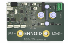
Open source BMS for 48V to 400V lithium-ion battery pack

I think V1.0 is good enough. It does what it is supposed to do. Of course, there are many fancy features that will be added in the future, but for now it works fine.

I'm not sure to understand your 6S serie and parallel stuff then... My BMS is exactly made for having battery modules that can be connected in series & parallel and a master which manage the whole thing uppon the predefined parameters.

You asked for some magic stuff like module autodetect and autoconfig... my BMS can't do that... would be nice thought, but it is still a far far dream...
 
No longer considering that.

Would be happy for each sub-pack module (6S just as an example) to be independently protected.

Say there were 30 of these modules, rotated between four different banks at different voltages,

so never mind about the whole-pack level for now,

just considering how to protect the 6S modules.
 
Protecting modules individually would require contactors on each module & MCU as well... raising cost & weight. Does not make sense I think.

With my actual design, each modules (from 4S to 18S) is equiped with one slaves board for temperature & voltage measurement, but all modules once connected together (several modules in series & parallel forming a battery pack) need only one MCU (master board) & one contactor for operating properly & being fully protected.
 
Well, that sounds just fine then, please confirm my understanding here:

Each module gets a slave board,

no MCU needed while they are not in use, just stored or in transit between banks,

it is the bank location that has the MCU + contactors.

If a single module is to be used as a standalone pack, then it requires a MCU and contactors as well.

If a larger bank with MCU in place, needs to grow from 4 modules to 12, later upgrade to 16, just need to manually re-configure it with the new xSyP configuration.

Rarely will bank voltage change, just the number of paralleled strings to add/reduce Ah capacity.

But it is the same modules used in all banks, whether

12V@40Ah
24V@300Ah
52V@20Ah or
72V@5Ah

If I reconfigure the sub-pack modules to a different xPyS layout, I assume each slave board also needs manual reconfiguration too?
 
Separate question,

Does your design accommodate multiple contactors per pack, separating the charge buss from discharge?
 
Your understandings are mostly correct, but there is no need to configure slave boards, only master needs to be configured. The slaves/modules are initialized automatically with new values, every time master get updated or initialized.

The master board has up to 4 contactors outputs (positive, negative, charger & cooling), but user can use only one main contactor if he wants.

The standard version of master is using two main contactors, this way precharge is done by switching the positive contactor (Persistent option), and the load is enabled afterward using the negative contactor (will only switch ON if precharge voltage has reached the threshold value set by the user). No need for an additional charger contactor as well in this configuration because charger is automatically detected when an appropriate external voltage is detected on the load terminals while Master is OFF.
 
Thanks a lot, I'm getting there. . .

ENNOID said:
there is no need to configure slave boards, only master needs to be configured. The slaves/modules are initialized automatically with new values, every time master get updated or initialized.
So, with an incoming set of slave-equipped modules, power down, connect the new modules and then power back up, can reconfigure the master before or after, right?

> The master board has up to 4 contactors outputs (positive, negative, charger & cooling)

no heating controls?

The charger contactor can be used to cut it's upstream input source off, say panels input to a SC, AC power on a shore charger, or a killswitch circuit on a genset or alternator VR?

I'll need to do some research on precharge, no idea what that's about.
 
no heating controls?

Always complaining lol. you seem like a funny guy aren't you?

I named it cooling, but the end user can rename it heating if he needs a heating contactor.

Other option, I could add another contactor output in the next revision, but so far, you are the only one requesting it...

The charger contactor can be used to cut it's upstream input source off, say panels input to a SC, AC power on a shore charger, or a killswitch circuit on a genset or alternator VR?

many options are possibles... only your imagination is the limit. Open source nature of the project means that anyone can contribute and adapt this BMS to his needs.
 
Not trying to be funny nor a pain, just asking, plenty of people live in cold climates where it would be easy to damage the bank charging too high a rate at too cold a temperature.

If that's already accommodated, sure just call it Temperature Management contactor and done!

And yes, of course a programmer with skillz can fork your code,

so are you saying that last issue would require that?
 
I'm from Quebec Canada, I know about cold believe me.

I think you are right, I'm gonna rename it Temperature Management contactor or maybe "do what you what with it output"

Yeah sure, anyone who want to improve the software is welcome!
 
Now that some Penthouse Boxes equipped with Master-BMS V2 have been shipped to beta testers, I'm already thinking about a lower cost, more compact & lower voltage version of this Master-BMS named "Master-LV" & would run the exact same firmware.

The specs would be something like:

- Limited to 150V max.
- Master/slave topology compatible with actual LTC68XX slave boards (12S, 15S & 18S)
- Single EV500 main contactor bolted onto the PCB
- Integrated precharge circuit & charger autodetect function
- Board mounted 500A(2500A pulsed) shunt sensor
- Some 12V outputs for external relays/contactors
- Isolated CAN interface
- OLED display + power button + serial outputs for NRF5X bluetooth
- USB configurable
- No isolation between power & logic for current, pack & Load voltage measurement, thus the 150V max. limit
- Will still require external 12V PSU for operating

Target cost is maximum 250USD with main contactor & 500A(2500A pulsed) integrated shunt current sensor. Overall cost is reduced by using only one main contactor & by removing some costly isolation IC used for voltage measurement.

That means that the cost for a 30S 500A(2500A pulsed) capable Master-LV + 2 slaves boards would be around 500USD... for a 18S single slave board system, the cost would be around 400USD

Target dimensions are 85mm x 135mm

Here is a small preview of the initial concept:
Untitled.png
 
nice design so far. but change the connectors on the board to locking models. otherwise you have to use goop to prevent them from shaking loose over time.
 
Thanks Flippy for your feedback,

For connectors, I found this:

2 pin, 2.54mm, gold plated:
https://www.mouser.ca/ProductDetail/Molex/70543-0001?qs=sGAEpiMZZMtVoztFdqDXOwZ%252B3K3gi96X

5 pins, 2.54mm, gold plated:
https://www.mouser.ca/ProductDetail/Molex/70543-0004?qs=%2Fha2pyFaduhkrELsSyc%252BzIuKEtMKXhOmproE9yj9wNE%3D

What do you think?
 
good replacement.

when possible try to turn the connector so it has as much space as possible for fingers to reach the locking pin. i often see boards where the locking pin ir on the side where it is right next to a tall component so you cant reach it properly.
example case is on the top left 2 pin and 5 pin for example.

or even better: re-arrage/route the board design so all the connectors are on 1 edge of the board, that would also make it a LOT simpler to do a conformal coating over the board and would give more freedom to unlock the molex and cable manage everything so nothign rubs.

dont know how locked in you are so far but if you have the space to make the connectors all on the edge it can make troubleshooting and just building the system a lot simper to cable manage.
technically its fine ofcouse but connector layout in a straight line on the edge is just a engineering guilding the lily kind of thing. i used to do it but my boards were usually simpler single layer or tru hole boards. nothing like these fancy smd type things those young folk grew up with.
 
Going with a 4 layers board, it would be easier to place all the connectors on only one edge of the PCB, but for a 2 layer board, that is more complicated. I can still improve a bit, but they won't be all on the same edge... I would go with 4 layers if the board could be made smaller, but the gain would be very small (if any) with a 4 layer because of the size of the current sensor & main contactor. I will think about it... maybe some other arguments would convince me to go 4 layers.
 
the main argument i usually stick to is so you can make massive ground/power planes wich makes routing simpler and you can use it as a heatsink if you put the ground plane as 2nd layer and IF something goes wrong you have a massive plane to carry the current. this usally means that you will blow the arse out of any faulty component instead of burning up the traces.
putting the data lines between 2 planes also shields it a bit more from outside crap, vechicles can be quite noisy enviroments.

ps: why put the board directly on the contactor? you are limiting yourself to a specific contactor instead of giving choice or placement of said contactor. what if i want a smaller or bigger contactor? then i am stuck with a board that is 50% bigger then it needs to be...
 
Integration was the main reason why the contactors are bolted directly onto the PCB. The footprint of this type of contactor is almost a standard at this power level and at 49.99$, they are way cheaper than any other lower power level options and not much bigger. The goal was that the end user has no fiddling to do when he buys a "Penthouse box" Just connect both battery & load terminals & ISOSPI coming out of the box and you are ready to go. Also, having less HV cables during assembly is a must. I'm using the contactor terminals to measure the battery & the load voltages. Coil ouputs are also just next to where they should be. User has also less chances of messing up the system. If a company or someone want a more compact design and needs custom hardware, we can talk and we can probably do it.

Some people might not want contactors or current sensor integrated onto the PCB and might prefer to do some tweaking by themselves. In this case, a 4 layer PCB would be very small and better suited... I'm planning to offer that one day not so far away.

Developing a BMS PCB is a faster and easier process compared to firmware development. Now that the firmware is up and running and that I know my system in almost every details, I can design different PCB approaches quite fast. Which one will turn best, time will tell.
 
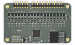
I'm placing an order today for slave board based on LTC6813 (18 cells in series per slave). So I should have them assembled in a few weeks in the worst case...

I have been able to keep the board with the same physical dimensions of 60mm x 100mm. Pin placement is also the same between all slave board (12S, 15S & 18S) except the total number of pins for temperature & cell monitoring.
LTC6813.png

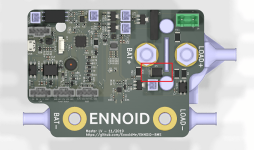
For master LV, I'm adding a TVS diodes in parallel to the main contactor on the PCB for additional safety. I haven't had any problem so far with surge voltage during high current emergency switching for master-HV with 7mm creep distance, but I think it is be a good idea to add some additional protection.

Creeping distance is reduced at 4mm with this additional protection. (Physical distance limited by the TVS SMC) More than enough for Master-LV, but for Master-HV i'm still not sure if it's enough if no conformal coating is used...

Do do so, I'm planning to use:
smcj440ca for Master-HV version (440V surge)
smcj150ca for Master-LV version (150V surge)

TVS placement:
Master-LV.png
 
I'm a little confused by the new LV design. Is the '+' side of the charger and load connected to "Load +" terminal? If so, is the contactor coil connected to "Charge" or "Discharge"? I have read through every post several times and am very interested in building this system for my 72v golf cart. Thank you for all of your hard work.
 
I'm a little confused by the new LV design. Is the '+' side of the charger and load connected to "Load +" terminal?

Yes, I designed the system for Master-LV such a way that load & charger can use the same terminals. I then use discharge coil output for both load & charging function.

There is a specific charge coil output as well on the Master-LV PCB if your application require a separate charger contactor/circuit.
 
This is a really cool project! 2 questions:
1. Is there any fault detection?
2. Is 400v a hard limit? I'm curious if this will work with a 112s pack (~450v)
 
1. Is there any fault detection?
- Pack overcurrent bidirectionnal
- Pack hard under & overvoltage
- Individual cell under & overvoltages
- Cell temperature max & min. soft limits, hard limits for temperatures will come with firmware update

Also, faults can be triggered by specific CAN bus messages

firmware code is open source, so you can contribute and code any other failsafe/fault detection function.

2. Is 400v a hard limit? I'm curious if this will work with a 112s pack (~450v)

400V is a self imposed limit. One should test it above 400V to know how it hold. In theory it should. all isolation chips used are rated well above 1000VDC. Creeping distance is approx 7mm at minimum without considering the TVS diode(4.5mm). Conformal coating would help at those voltage level.
 
Happy new year to all and want to thanks early adopters for their support.

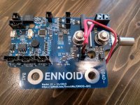
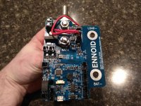
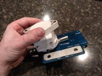
I have been busy lately and I had no time to post update. Here is a few pictures of hand assembled prototype ENNOID-BMS master low voltage version with bolt-on contactor & current sensor:

IMG_20191231_172525.jpg

IMG_20191231_172342.jpg

IMG_20191231_172322.jpg

I will do some testing soon in 2020... see you there!
 
Back
Top