Open source BMS for 48V to 400V lithium-ion battery pack

You mean different behavior of the BMS when you use pulse or toogle option in the ENNOID-BMS app?

I'll review this part in the firmware code this week end and will try to figure out why this bug could happen...

For the schematics, sure!
 
Exactly. I want to use the toggle setting due to wiring through a key switch. In this case though, with the switch off, when I connect the charger, the bms comes on briefly, but in under a second it shows "Bye" without ever engaging the charger relay. If I leave the switch on, charging works fine for some period of time. It always has an error before charge completes. I haven't figured this out yet either. Is there any way to determine what actual errors are ocuring?

I finally, after many hours of trying, got the firmware to compile using cubeIDE, but there were problems. The compiled bin file is roughly 50% larger than yours even though I made no changes. This causes the app to time out trying to load the firmware so I loaded it using STLink and though all was well, but that seems to cause problems with the eeprom. The firmware will run, but no settings are stored.
 
Exactly. I want to use the toggle setting due to wiring through a key switch. In this case though, with the switch off, when I connect the charger, the bms comes on briefly, but in under a second it shows "Bye" without ever engaging the charger relay. If I leave the switch on, charging works fine for some period of time. It always has an error before charge completes. I haven't figured this out yet either. Is there any way to determine what actual errors are ocuring?

Many things can go wrong with your custom BMS hardware config & battery pack. When you keep the key on and charging starts, do you see the battery logo with the charging symbol on the OLED and do you see charging enabled on the ENNOID-BMS app? Before the BMS shut down, does it start the balancing process? Normally, the battery charging logo and balancing should be written on the top of the OLED. The app should show balancing as well.

Which version of the schematics are you using, Master-HV or Master-LV? One thing that could cause the charging process to stop could be related to the pack voltage measurement. If the measured voltage gets above the 4.2V x cells in series, then the BMS will detect a fault. In this case, try to reduce a bit the "Pack voltage factor" to stay below the maximum pack voltage. There is also the charger enabled threshold that could cause the charging to stop if the charge current is too low.

I finally, after many hours of trying, got the firmware to compile using cubeIDE, but there were problems. The compiled bin file is roughly 50% larger than yours even though I made no changes. This causes the app to time out trying to load the firmware so I loaded it using STLink and though all was well, but that seems to cause problems with the eeprom. The firmware will run, but no settings are stored.

I don't know the final size of your bin file, but even at 50% bigger, I don't think it should be a problem. MCU has 256k and my bin file has 85k, so approx 1/3 is used by the program itself. There might be something else going on with the compiler or your settings... Despite this, I could probably add some seconds before timing out on the ENNOID-BMS app as well.
 
With the key off and the charger is connected, it shuts down almost instantly before even trying to charge. The "Charge"" relay is never engaged and the screen only displays "Bye".

I am using the LV version.

My compiled file is 128k and it times out when trying to load around 75%. I changed some settings in the compiler and got it down closer to 102k and it times out around 96%.
 
If the key is left ON, it will charge. It''s set to charge 18 cells to 4.15v per cell. It always shows error right around 4.0v per cell. It only displays error so no idea what the actual error is. It would be super nice if the actual type of error would show up in the debug console.

Thanks so much for your help.

Did you receive the schematic for the economizer circuit I sent?
 
Yes I received the schematics.
It would be super nice if the actual type of error would show up in the debug console.

More error code for helping troubleshoots will be implemented one day.

If the key is left ON, it will charge. It''s set to charge 18 cells to 4.15v per cell. It always shows error right around 4.0v per cell

I think, you don't understand how the BMS should behave. When you turn the key ON, the BMS will boot, do some checks and will allow discharge. If you connect a charger on the load side during operation, the BMS will think that you are in regen mode. This is not "charging mode" at all, this is called regen! The charging sequence is not established, only normal operation...

but:

As I said earlier, the error you get when you do regen is probably because the BMS get an overvoltage detected on the pack voltage measurement channel or on a single cell voltage level that get above the maximum cell voltage allowed. The "pack voltage factor" is probably set too high...

With the key off and the charger is connected, it shuts down almost instantly before even trying to charge. The "Charge"" relay is never engaged and the screen only displays "Bye".

This indicate me the problem mentioned above: The charging sequence never starts...

I think you have a problem with your "load voltage" measurement circuit as well. The charger detection circuit works, but the detected voltage on the load or charger input is not high enough to allow charging... then the BMS goes in shutdown. You need to have both "load voltage " & "Pack voltage " measurement circuit functional & the "voltages factors" adjusted properly to get the BMS working correctly... also the measured charger/load voltage must be above the pack voltage. With the original Master-LV schematics, those values should be around:

Pack voltage factor : 3.5
Load voltage factor : 50
 
I
think, you don't understand how the BMS should behave. When you turn the key ON, the BMS will boot, do some checks and will allow discharge. If you connect a charger on the load side during operation, the BMS will think that you are in regen mode. This is not "charging mode" at all, this is called regen! The charging sequence is not established, only normal operation...

It certainly seems to go into charging mode. The load contactor disengages,the charge relay engages, and the screen displays the charging icon.

I think you have a problem with your "load voltage" measurement circuit as well. The charger detection circuit works, but the detected voltage on the load or charger input is not high enough to allow charging... then the BMS goes in shutdown. You need to have both "load voltage " & "Pack voltage " measurement circuit functional & the "voltages factors" adjusted properly to get the BMS working correctly... also the measured charger/load voltage must be above the pack voltage. With the original Master-LV schematics, those values should be around:

Pack voltage factor : 3.5
Load voltage factor : 50

My Pack voltage factor:3.557
My Load voltage factor:48.869
 
Ok, I was wrong with my first assumption then, but it still shows me that the charging mode is not engaging as it should... there might be a problem with the load voltage measurement circuit. Also, when you connect the charger, the type of switch (toogle or pulse) has no impact on the BMS. the switch stays OFF in both case...
 
I tried a very simple test to narrow down the problem. I used the BMS tool to load two different configurations with only 1 single difference, the button configuration. Test 1 this was set to Toggle. With everything idle and switch in off position I connect the charger. Display comes on and then immediately says "Bye". None of the relays ever close. I tried this at least 20 times with the exact same results. Test 2: the only change was to use BMS tool to change the button setting to Momentary. Testing in the exact same manor as before, when charger is connected, the display comes on and displays the Charging icon. All seems well with the momentary setting.

I know you have told me over and over that the switch has nothing to do with the charging process, but this one setting has a drastic effect on the behavior I am seeing.
 
OK, I believe you. I will review the code when toggle setting is used. This is for sure a software problem with toggle switch option.

thanks for reporting the bug.
 
@ fillupc : I fixed your toggle switch issue at charging in the V1.1 firmware

P.S. You will need to download & use the ENNOID-BMS tool V1.1-pre with the new firmware
https://github.com/EnnoidMe/ENNOID-BMS-Tool/releases

Thanks for reporting the bug
 
Also, I just changed this morning some settings for charging, I relaxed some safety protections that were maybe problematic when the voltage monitoring settings are not perfectly set-up.

Also modified many little things, so balancing should be ok now...

Let me know if your charging issues are still happening.
 
I should have 10 x Master-LV board ready on monday next week and several LTC6811 slaves. I do have a couples of LTC6812 & LTC6813 boards left as well.

The 2 weeks manufacturing lead time warning on my website is to give me some buffer between new orders, but this week should be ok for immediate shipping with the actual inventory.


For the ones interested, I started a blog on my website that explain how to use the BMS:

https://blog.ennoid.me/2020/02/ennoid-bms-setup.html?m=1

More info will come in the future on this blog.

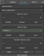
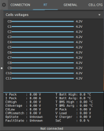
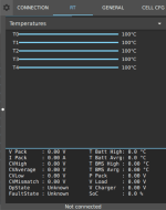
I have also been able to get an app running on my android phone. Next step is to do some testing in order to see if I can get communication between the phone & the BMS over bluetooth/UART. This app will be useful for configuring the BMS wirelessly and will be also good for data logging with the realtime data, cells voltages & temperatures on a nice touch display:
Untitled.pngUntitled2.png

Are there any wishes or idea about functionnalities that should be implemented on this mobile version of ENNOID-BMS tool?
 
I have been asked several time through e-mails or PM for developing an e-bike oriented BMS based on the actual ENNOID-BMS open-source firmware & software. Keeping all functionalities regrouped on the same board (No slave board, FET switching & integrated power supply) Similar to DieBieMS with larger current capacity & with LTC6813 IC which is good for up to 18 cells in series. Going up to 20 or 24 cells with 2 x LTC6811 IC would be nice, but the problem is related to the large gap in size & cost for the power supply beyond 75V pack/100V peak...

I have been thinking about it for a while now and I am still not convinced I could make a profit with such a project. There is already the 16 cells max. "Tiny BMS" on the market that does the job already. There might be a few things that this BMS does not offer, like integrated precharge, high current with internal fets, high side power FET control & not being open-source, but the product looks good. On the software side, it seems there are some functionalities offered by the "Tiny-BMS" that are still not implemented in the ENNOID-BMS firmware which is also good..

The main problem related to such small BMS is the low selling price. I don't think I could offer all functionalities and high current capacilities for less than 250USD per unit unless being a large company producing thousand of units per week... Also, it is always temping for e-bike users to buy a cheap chinese BMS that will get the job done at the expense of some trade-off.

I don't know what to think about it really, the only reason that I would work on such a project is the larger user base that I could get with an e-bike oriented version. People in the e-bike community might get more involved if a cheaper version was available.

Any suggestion or idea on that topic anyone?

Thanks
 
I don't have any evidence on the question of market size, unit cost, or profitability but I would love to see this product.

The VESC ecosystem is starting to see the development of VESCs with powers ranging from modest to the Axiom high power. It would be great to see a spectrum from the modest DieBieMS through the massive Ennoid-BMS with some choices in the middle.

The main benefits of a 6813 Ennoid/DBMS unit over the TinyBMS would be CAN bus ports, screw in attachments, and open schematics and code. I've been using the TinyBMS for about a year and it works well and has good documentation on the protocols. However, I would pay a premium for a 14s device that could be integrated with a VESC on a CAN bus.

It was straightforward to configure an Arduino/TFT dashboard for a VESC/DBMS system owing to the CAN bus integration.

I haven't tried the uart2can device sold by Energus, but their modbus implementation has a bug where the device responds to any request on the bus, regardless of ID.

Unfortunately, none of this is relevant to whether the market would support the large engineering and production costs of such a device. There are some ebike folks that are interested in open-source products but I see several battery builders choosing a BMS primarily on price where it would be hard for this to compete.
 
I had some time to work on the schematics + PCB part placement today...Design is not finalized, but will be very similar to DieBieMS

ENNOID-BMS-SS (SolidState)
- 70mm x 145mm
- 4 layer board
- 3 main discharge 100V rated FET (Instead of only 2 on DieBieMS) ~120A continuous
- Using the same ENNOID-BMS firmware & software

Features:

- 10 to 18 cells series monitoring + passive balancing 33ohm resistors per channel
- 9 temperatures sensor channels available
- On-board 3.3V power supply taken from the battery pack voltage
- Load + Battery Voltage sensing
- Current sensing
- Integrated predischarge
- Board mounted Fuse on top right (Not shown)
- High side switches (all switches use N-channel FETs on the positive terminal so ground/negative stays connected)
- Charger detection circuit
- Separate charge/discharge circuit
- Charge bypass FET for reducing heating during high current charging
- Bolt on 180A terminals wurth #7461383

I/O: serial(UART/Bluetooth), CAN, USB, I2C(Display), Power button
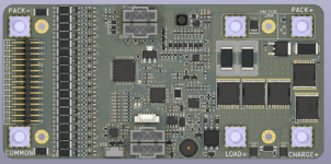
Screenshot from 2020-06-07 19-35-21.png
 
Many people these days would like to run 24S, which can go a bit over 100V fresh off the charger.

And apparently even quality genuine branded FETs can vary greatly in their ability to abide pushing their rated limits.

So if it is possible to target accommodating say 120V, that would be a great competitive advantage.

wrt current, don't go nuts with a half dozen variants, once past say 200 battery amps maybe just offer the least expensive lowest amps model as alternatively controlling external contactors, disabling the OCP, they can just use fuses for that.

Also common-port vs separate preference shojld be accommodated.
 
Going 24S would increase the price & the size by a large factor as I posted previously (power supply size & control IC voltage tolerance) even 18S is a bit over the limit, 16S is probably the limit for large current & with 100V IC... No magic IC exist yet above 100V! Unless someone shows me how to do it for small & cheap...

On the other hand, there is already ENNOID-BMS Master & slaves for higher power level...
 
Looks very good to me. Having all the connectors on the top side is more convenient for installations. Also, the larger pitch connectors makes it easier for hobbyists to crimp their own wiring harnesses.
 
What about the BMS basic functions only. But with nice features the aliexpress BMS dont have.

1. Let the power flow through a relay. I do not se a reason current passing the BMS.
2. Easy programmable cut-off voltages, like 4.1V -> 3V.
3. Protecotion functions will trigger the relay and thus cut the battery off.
4. Over current will be made with a fuse right after the battery
5. Have a good balancing solution with enought balancing current.
6. Saving the MOFSET gives room for a nice pre charge resistor.
7. Optional: Having a charger connection with a fuse onboard.
8. Also optional but worth litte brain power. You can offre a logging functionality. All technical stuff of the battery. How many cycles, how high was each cell charged and how low discharged (in avg.). Measure avg. discharge rate. Temperatur protections. Collect the ambient temperatur, with possibility to use external temp probe. People buying this BMS will be able to compare their packs and can give others good review of cells.

No need of connecting a LCD, measure the speed, or a fancy App (exclude point 8 ). This is the job of other components. How often one is setting the values of the BMS. After first weeks of use, there is no need anymore.

I think with point 8 you really can make a difference to other BMS. The other points would be nice :)

What do you think about?
 
Well, the only point I agree with you is #8. BMS would act a bit as a VCU if your idea was implemented properly. I think the phone app would be a good way to do it without adding cost.

Other points you are mentionning are already available/implemented with Master-LV or HV boards... Removing some functionnalities on this latest e-bike oriented version would reduce the cost by a marginal extend. Only a few bucks would be saved. So cost is not a reasons to get rid of some functionalities... External relay is a bad idea as well if you want to go cheap and compact...
 
ENNOID said:
I had some time to work on the schematics + PCB part placement today...Design is not finalized, but will be very similar to DieBieMS

ENNOID-BMS-SS (SolidState)

this looks really cool, might be the perfect solution for my project (~130 cell mobile battery pack). do you have an estimation for cost yet? i mean, i feel bad comparing this to chinese bms at all, but your main -BMS project is prohibitively expensive for my hobby project.

thanks for info!
 
Back
Top