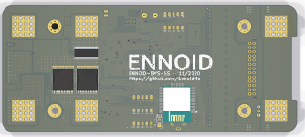
Open source BMS for 48V to 400V lithium-ion battery pack

Bill of material alone is a bit more than 100USD when counting with 100 Units. BOM goes down to approx. 90 USD with more than 1000 units. I don't think I can include the development cost + cost of manufacturing + small profits without staying at approx 200-250USD for now...

My goal isn't to beat the chinese BMS on cost at all with this e-bike oriented version...it is to offer something different with better specs/features. Something open source that you can trust and rely on. VESC has a similar approach too..
 
ENNOID said:
Bill of material alone is a bit more than 100USD when counting with 100 Units. BOM goes down to approx. 90 USD with more than 1000 units. I don't think I can include the development cost + cost of manufacturing + small profits without staying at approx 200-250USD for now...

My goal isn't to beat the chinese BMS on cost at all with this e-bike oriented version...it is to offer something different with better specs/features. Something open source that you can trust and rely on. VESC has a similar approach too..

I know, i know. I would be willing to pay "more" for my hobby to have it OS and the ability to control all the parameters, but 4-6x i can't justify to myself ;)

For larger installations the prices are ok I guess; there probably isn't a (good) Chinese alternative for those kind of projects anyway; and commercial solutions are very likely more expensive. So in that case it makes more sense.

I can hand solder 0805 smd but your rendering looks like this is above my abilities so I can't even cut costs that way unfortunately..

Still I am very impressed by your work and will follow and see where this is going in the future ;)
 
Thank you.

FYI, I'm using 0603 size which is not much harder than 0805.

Prices might get lower one day, but for now I don't think I can produce for lower than that. There are a few things that I could do, like removing the quite expensive wurth connectors for bare soldering pads (user would have to solder main cables) and just using two main mosfet with lower amp rating (thus lowering current capability), but it would reduce the BOM price by 1/4 in the most...
 
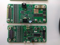
I finally got some time to almost finish the assembly of the all-in-one solid state version.
Upper one on the picture is the 18 cells in series capable ENNOID-BMS-SS, below is the original DieBieMS:
IMG_20200716_103024.jpg

Only a few parts are missing ordering them today and should be able to test it in the coming week....
 
ENNOID,

Sorry - very late to the party. I am going to have to go back and re-read your whole thread but I have to say - I am a little disappointed you used the LTC over the TI bq76PL455. I was one of the designers for the TI part, so it would have been fun to see you use it (really, I was). I "left" TI right as the 455 was being released and design wireless battery chips for cell phones for a different company. I just started thinking I should get back into messing around with EVs and came across this thread. Anyway... thanks for the info.
 
Hi,

I think the LTC lineup has better features and flexibility than the IC you mentionned. Despite this, TI will soon release a new generation of BMS IC bq75614 which might be even better,... there is also infineon who have released an ltc6811 equivalent, but I am not so sure about using it...
 
This is a very cool project, and I have some ideas that this will be perfect for. In the short term, the SS looks like just the ticket for my smaller e-bike projects.

Does the ENNOID-BMS-SS work without enabling or installing the main MOSFET/Contactor? I have a project right now that could use a good, configurable BMS just for charge management.
 
ENNOID-BMS-SS is not functionnal yet, I had some issues with the charge pump on the BQ76200. I have not been able to enable the FET switches because the charge pump is not reaching the +14V that it normally should, stuck at 5-6V so UVLO is triggered. Seems like there is a leak somewhere and I had no time to test it further.. I will compare with the second populated board soon. it is a very weird issue that I was not expecting... However, the rest of the board works as expected. I will spend a few hours on it soon. I have been very busy lately and no time to work further on this project.

In the mean time, I found a way to ditch the 100V limited BQ76200 IC used for high side fet drive and also found a way to go above 100V with the power supply without increasing the cost by much (maybe 5$ more expensive in total) and same size (No large, heavy & expensive transformer). This will allow up to 24S solid state version capable board even maybe a bit more... Some people here will be happy I think. Only issue now is the main fuse size/price related to the voltage limit...

Does the ENNOID-BMS-SS work without enabling or installing the main MOSFET/Contactor? I have a project right now that could use a good, configurable BMS just for charge management.

You can use the BMS for charging only. In this case, you could have a board with only the charging FET switches populated You would then save the cost of 3 main FET @3$ each+3$ load+ connector. But doing so, you won't have the predischarge function and fuse protection if not going throught the BMS for discharge...
 
ENNOID,

thank you for all of this fantastic hardware and all of your amazing effort. I'm sure youre very busy, but I was wondering if you have any videos showing how the ENNOID-BMS configuration tool works. My application would be to do balance charging of a 24S set cells, that are 16Ah, and 12C. I plan to use for of these packs:
https://rcbattery.com/liperior-16000mah-6s-12c-22-2v-lipo-battery-with-xt90-plug.html

and before I purchase the Master-HV and slave boards I was hoping to see how to do the software configuration. Do you have any videos or additional documentation?

thank you again!

o
 
This will come my friend. I'm a bit reluctant about doing a prommotionnal video right now without everything in place. My idea is to show a whole product line of BMS & custom battery modules for DIY projects. I might be ready to pay for a professionnal at this point for the video montage. Lot of things are slowing me down. My latest newborn is taking me a lot of my time. I might even cancel orders on the website for a period to focus on R&D and tomake the video happens.

Until there, I will try to not disappoint anyone for being so late at delivering.
 
Update:

There is a new firmware & an new ENNOID-BMS tool app V0.12-alpha available:
https://github.com/EnnoidMe/ENNOID-BMS-Tool/releases/tag/V1.2-alpha
It is still in alpha stage because some planned features have not been tested or not functional yet, ex: LTC6810 support & mobile BLE GUI.

Other development:
- The solid state 18S ENNOID-BMS-SS is now working fine and under testing.
- The firmware & tool app now support external temperature expansion boards. Several formula SAE electric project were asking for additional temperature monitoring channels with ENNOID-BMS. User can now have 72 additional temperature sensors reading through an isolated I2C interface. We are now doing some testing with those expansion boards. So far, they seem to works great.
 
Second batch of the 18S-solidstate 100+A was functional, but some little details were not perfect.
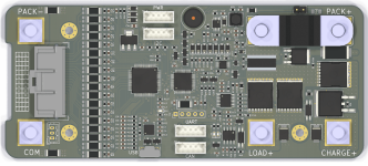
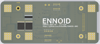
The new 3rd iteration will be smaller & cheaper than initially planned with 60mm x 140mm & with a 75USD$ BOM (55$ for charge only+solder pads) and several improvements :
Untitled-1.png
Untitled2.png

Improvements :

- New circuit for the high side current common mode voltage, with P-FET instead of voltage divider, it should be more precise with a new technique from TI described here:
https://www.ti.com/lit/an/sboa198/sboa198.pdf?ts=1604858193761&ref_url=https%253A%252F%252Fwww.google.com%252F

- 2 row x 13 pins molex micro-clasp or Igrid 2mm pitch connector for cell balance connector will be more compact and self lock (Still looking for better options)

- Will be able to solder the power cables directly, thus possibly saving the cost of the quite expensive 6 x Wurth connectors.

-Smaller size, identical size and same mounting holes position as DieBieMS

- For lower profile, the 5 pins connectors are moving to JST PH instead of Molex SL

- Will be able to use the BMS for charging only, thus it is possible to save 4 additionmal main FETS & the precharge FET + resistor

24S-solidstate version is also in the works. Size will be the same, but dual sided PCB is needed for balancing circuits and a bit pricier unfortunately.
 
Super cool project!

Forgive my ignorance, but what additional functionality does CAN provide? I've only ever used 'dumb' BMS...
 
CAN is a communication port actually used for advanced functionnalities like:
- Throttling/limiting power on the ESC when the battery is almost empty or almost too hot for operating
- Throttling/limiting power on the charger when the battery is almost fully charged, too cold or too hot
- Throttling/limiting regen power on the ESC when the battery is too cold or too full
- Communicating battery status with other external devices ( CAN display, CAN sensors, isolation fault device, ESC, charger, etc)

and for implementing any future cool project/ideas that would requires CAN communication.
 
This is great progress.

- 2mm pitch for the 2x13 would be great if you can find a part. Below 2mm gets very difficult to reliably crimp for mortals.

- Having a pad footprint that allows direct solder or Wurth terminal is good for flexibility and cost reduction.

- Matching the old footprint and mounts helps preserve existing designs for cases. The backside shunt and FETs are an elegant way to get some real estate back without a lot of complexity.

- Moving the 5-pins to JST PH should shave a couple millimeters of stack height, which could be useful for some installs.

Really promising. Thank you.
 
I'm getting better with connectors after spending many, many hours looking for the right connector for my projects.

Not an easy task, so many options and things to consider:
- Pitch
- Dimensions
- No of circuits
- No of row
- SMD/through holes
- Gold/tin
- mating cycle
- reflow tolerant
- Straight or right angled
- Lock
- Price
- Availability

Do I forget one?

With 30mm as the maximum connector width, the only options left are the Molex Igrid & micro-clasp with a 2mm pitch. Igrid has a lower profile and has gold plating pin options. Drawback is that they are not reflow tolerant & are through holes connectors

The best choice would have been using a 3mm pitch WR-MPC3 from Wurth or the more expensive molex microFit with gold plating: those are SMD mount & reflow tolerant, but even a 20 position connector is too large for the board design... also, no options above 24position connector
 
Do you have any plans to make a stand alone BMS that doesn't require a Penthouse? Most of my use cases will be high power e-bikes, but the Penthouse is a little bit overkill (sorry if you already touched on this, it's a long thread!). While I certainly don't mind dealing with Chinese companies, I'd rather spend more money supporting those that are developing innovative products.
 
@stiffler359:

Just look a few comments above...

Targeted market for the solid state 18S version still in development is in the range for high end ebikes and has everything included on a single PCB. No need for any penthouse box there...
 
@ennoid:

How long until you have the 24s ready for testing, and will you be looking for beta testers? I would gladly cover the cost of parts to help out your project. For reference, most of the packs I plan on building over the next few months will be 20s5-7p, using 2170 cells. Cheers
 
Price will be probably a bit above 200USD per unit.

24S version will not be ready before several month. Christmas holidays are coming and 18S version 3rd iteration is still not tested. I'm still waiting for some feedback from the 2nd iteration before ordering 3rd batch.
 
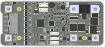
Some improvements again on the 3rd iteration 18S unit that will also be included with the 1st iteration 24S unit:

- Added an NRF52 Bluetooth module option on the backside, will be more practical than USB for monitoring & configuring
- Added humidity sensor (For monitoring the moisture in the battery pack enclosure )
- New improved power supply unit for ultra low IQ & up to 1A 3.3V capable
- Optional connector (SW) for disconnecting power supply from battery (Quiescent current is now only 6uA for long term storage when SW is disconnected)
- Several small enhancements to improve power consumption at iddle
- New CAN bus IC compatible at 3.3V, no need for external 5V power supply anymore

Untitled.png
Untitled2.png

I will test the units with VESC to insure compatibility over CAN bus. I have a custom BESC G2 for doing tests with up to 24S config.
Goal is to sell kits of ESC & ENNOID-BMS configured together
 
Back
Top