PAS signal altering

Quezacotl

10 mW
Joined
Jul 4, 2016
Messages
22
Location
Finland
Hello!

I'm having a problem with this simple thing, which is'nt so simple afterall.
I'm trying to alter the PAS signal. Actually reducing it, so that hall sensor inside the motor would output proper signal. It's installed the same way as the hall-sensors that tell the motor position. (It's a motor that had controller and PAS integrated, but now only PAS)
What it does now, is that it just nudges a little forward, presumably because there's so many magnets(too high frequency).

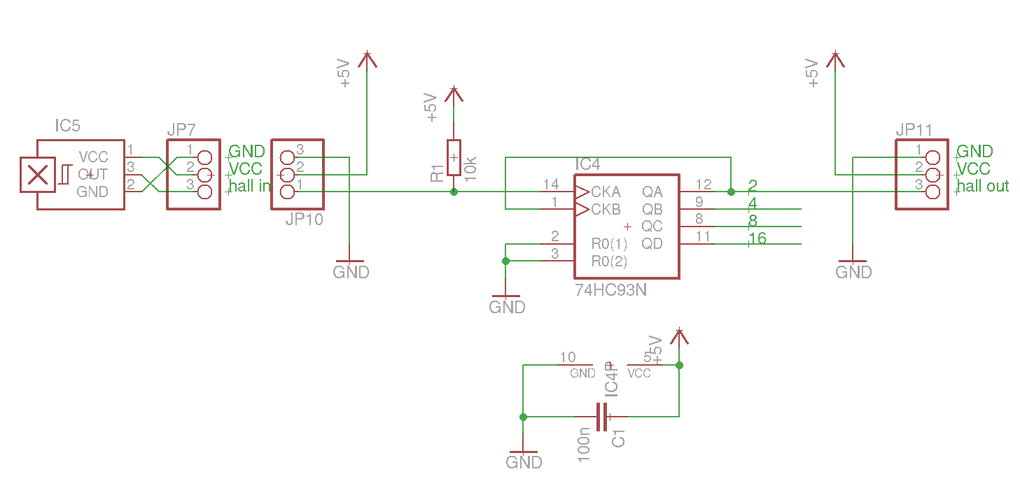
I know i could just use 74HC93(counter) etc. for doing this, but i want to make it adjustable with push buttons.

I made simple arduino code. It monitors when the hall is going low and counts until it can tell the controller to switch between HI/LO. The lost pulses is adjustable with two buttons.
The code is working when i try it on breadboard with LED and hall sensor, everything good, but when i put it to read from the motor hall and output to controller PAS input, it does absolutely nothing.
https://pastebin.com/nN3RvtNV

I tried also code that it feeds the controller a signal like (write HI, adjustable delay, write LO, adjustable delay), and it responds by spinning the motor momentarily because maybe too crude code, but proves that the chip can give signal.
 
Do you have any pull-down or pull-up resistor in your pas input. Otherwise it float and you cannot get proper reading when circuit is in noisy environment like ebike. If you don't have any resistor, you can also activate arduino internal pull-up resistor just change pinMode(pasIn, INPUT); to pinMode(pasIn, INPUT_PULLUP);
 
Quezacotl said:
I made simple arduino code. It monitors when the hall is going low and counts until it can tell the controller to switch between HI/LO. The lost pulses is adjustable with two buttons.
The code is working when i try it on breadboard with LED and hall sensor, everything good, but when i put it to read from the motor hall and output to controller PAS input, it does absolutely nothing.

Which controller?
 
Yea i have a pull-up on the input(hall), I saw requires it when the voltage was too low in high state. Thanks for the internal pull-up tip. Now i have that enabled instead in external, and it works just as good as the external.

The controller is just a normal chinese.

I put the chip back to jumper board(what you call it) to confirm it still works, and no problem.
Now i noticed that when the chip is connected to the controller, the output is always high. So that seems to be the core problem right now.
I know the wires are in right order because when i measure the signal wire when connected, it behaves right, alternating hi/lo when turning the wheel.

(And i have a 100n between 5V&GND!)

EDIT: Now when i added a LED to the output, i noticed that it's working for few pulses, but when i start spinning, it seems to crash leaving output permanently high.
I have Attiny13A connected. I doubt it has nothing to do with that, but i'll try for the sake of it to use arduino nano...
 
Cadence, as in frequency? Yes frequency/pulse based. I think there was originally a capacitive sensor sniffing tooths near the axel. It was closed source like commercial things are.
I think there's like 36 or more magnets inside the motor, and isn't the normal pedal plate like 6-12 magnets? So then i would need to ideally divide by 3 to 6. The chinese controller says the PAS is 1:1 whatever that means.

Now i tried to replace the arduino with simple counter chip(74HC93), but it didn't work either. It wasn't doing anything. I tried all 2/4/8/16 divides but nothing. I measured the chip when connected on bike that it outputs the same than the hall sensor gives but just stretched, signal is HI/LO as long as the hall says the next HI/LO.
I also tried the arduino nano, but of course nothing.
Chinese controller outputs about 4,5V. Also the hall sensor outputs same. chips in middle(arduino or 7493) do the same and are powered by the hall line power. The power is not dropping, it's got enough power to light many many LEDs and chips.

Without anything between, it atleast tries to boost on very slow speed(you'd fall), and if wiggling a magnet in front of a hall sensor connected to PAS wires, it spins as long i keep steady hand.

Here's how it's connected. The hall sensor is 3144.
8pj210K.png
 
Quezacotl said:
Cadence, as in frequency? Yes frequency/pulse based. I think there was originally a capacitive sensor sniffing tooths near the axel. It was closed source like commercial things are.

What's the end goal with respect to how the bike functions? e.g. as whenever the motor/wheel turns, it provide a signal to the controller to provide assist?

Also, how do you stop?
 
To it to behave like it used to. PAS in motor. It's Cube brand.
I assume there was something like if it starts slowing down(minimally), it cuts the assist.
I realise it's a closed loop without said cutoff. I'll figure that once i have got this to work.
 
Quezacotl said:
To it to behave like it used to. PAS in motor. It's Cube brand.
I assume there was something like if it starts slowing down(minimally), it cuts the assist.
I realise it's a closed loop without said cutoff. I'll figure that once i have got this to work.

OK, but it sounds like you believe the original PAS wasn't based on pedaling, but the wheel turning, is that correct? Never heard of pedal assist that isn't associated with pedaling of some kind, but it's an interesting concept.
 
Yea. It's indeed interesting. There's only motor, battery, speed sensor and wireless remote to show stats. I confirmed that minimum to make it function is motor and battery. Normally you can choose assist levels from the remote, but you can also set the system on emergency mode(if remote has dead battery), so it works only on medium assist. Speedometer is only for stats and not for anything else.

But this my problem excludes that system entirely because it's removed.
 
Now i tried to use opto between, and with divide by 2, it did the same as without any circuit. Divide by 4, i could hear the motor activate, but doesn't do anything and same with 8 and 16. Atleast the opto made it to "work".

This starts to seem like i need a signal multiplier instead of divider. Sounds crazy. What do you think?
 
Back
Top