SwampDonkey said:
I have this same controller sold as the "luna hot rod Sondors" controller. Can you help me wire this to an Eprodigy Logan? I cant even get the controller to power on so I can start deciphering the motor wires. Any tips?
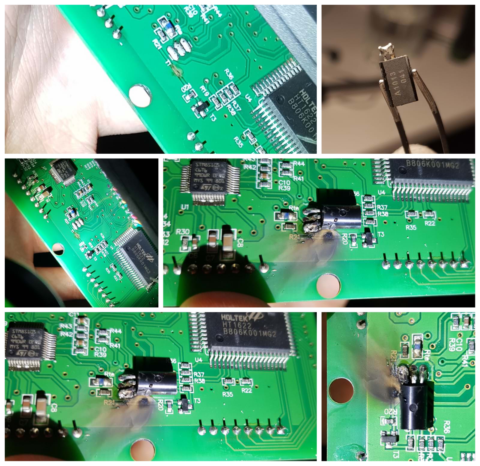
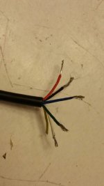
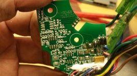
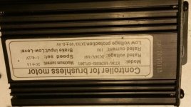
I have a Luna Hot Rod controller. It was intended to replace the stock controller in the original Sondors Fatbike. I believe mine was the 25A model they no longer sell, but it's a KT36/48ZWSRM-SLSD02. It was intended to work with the stock Sondors Harness, except I didn't own one either. When I bought it in 2016, I thought all KT harnesses were the same. They are not.
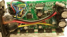
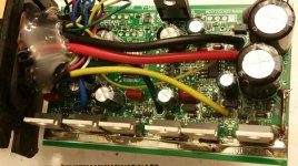
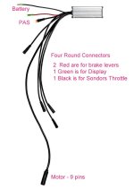
The 9 pin motor (female) cable on this controller is a standard pinout though, and will fit any 9 pin motor that uses the round (male) plug. I believe it's a 9 MOSFET controller, not 6 MOSFET.
Anyway, mine was started by crossing the LCD3 display's start wire over to where the start wire from the Sondors throttle went. I put that all inside a home made harness. Lost my notes. After that, I bought controller/display/PAS/etc all in one combo. To much work to wire disparate vendors.

")