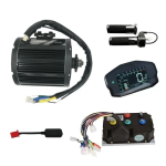
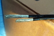
Qs138 v3 70h - phase wire upgrade

Eastwood

100 kW
Joined
Jan 13, 2021
Messages
1,479
Can anyone share their experience with upgrading the the phase wires for the QS138 V3 70h to a larger AWG? I typically do this on my hub motors but was curious what size wire has been able to be fit? I haven’t opened the qs138 before so I’m not sure how thick of wires we can go with.

Or does anyone have pictures of the open motor? I’ve seen them on here before but I can’t find them through using the search engine.


The QS 138 v3 "90”H seems like a great option as well but I’d rather have the lighter motor.
Thinking out loud, but it seems like there's a point where it becomes a case of diminishing returns. Conductors separated in free air have greater current capability than ones bundled together due to reduced heat dissipation. Similarly, conductors running through conduit or other enclosed path have a reduced capability for the same reason. Running several fat conductors through a small metal is the worst of both worlds.
I've seen forum threads on the benefits of using fatter conductors outside of the motor to wick away heat. I've wondered how beneficial that might be, even with a little skepticism. Then when I got my big soldering iron for soldering big connectors, I realized how fat copper wires not only conduct more current, but also how efficient they are at transmitting heat. You could put the iron on one end, and in no time the wire will be too hot to hold 6 inches away. Maybe a foot or so of 2 gauge jumper cable conductors just outside the motor would work as a good heat sink?
 
A weller iron from home depot of the 180/240w dual wattage variety, plumbers iron, home depot or a good soldering iron, I doubt a 60w cheap iron would suffice on those conductor diameters.
The big phase wires and big winding wire requires lots of heat.
get underground heat shrink, double or triple it up.

Hammer tip for the soldering iron for what looks like 6-8awg wire. blow torch the wire could help the iron heat all those beefy wires up, but it may also add carbon, so its a delicate task.
14awg or 16awg solder diameter, as you need bigger diameter solder otherwise with the thinner solder you dump too much solder in, have to bring more, or shall we say unwind more solder out while in the middle of the doing the task at hand.

Setup and positioning and having the right tools is everything. Like a 3rd hand the rc guys use and a good solder iron stand that can be cheap, just tape the stand down when using it. Put on some big alligagator clips on the 3rd hand for the big wires. Love it.
 
Last edited:
The nice thing about this styel of motor is that unlike a hubmotor you don't have to fit it all thru an axle, so you can go about as big as you want. You just have to increase the size of the hole in the outer case to fit that and any grommet/etc you use to keep the wires from pressing their insulation onto the casing.

AFAICT it's an inrunner, so you aren't needing to worry about a spinning case likea hubmotor, just open the endcap on the non-drive side and do wwhatever wiring work you need to. Enlarge the hole (probably a D-shaped cutout) to fit your grommet and wiring, and away you go.

As E-HP notes, wire exposed directly to airflow will better shed heat, so if you can leave the outer jacket off all of the phase cabling from motor to controller except where you tie it down to the fframe/etc, it'll perform better than if it's isnide the heat-insulating cable jacket.

Iff you can run the three wires separately with an air gap between them rather than tied down together, it will be even better.

Iff you can run them out of the mtoor via three separate cutouts, witha fourth cutout for all the signals, and run these threee wires plus signal bundle as four separate paths to the controllerr, you'll get better heat shedding *and* signal isolation to reduce induce-current interference.

1691811772953.png
 
Thinking out loud, but it seems like there's a point where it becomes a case of diminishing returns. Conductors separated in free air have greater current capability than ones bundled together due to reduced heat dissipation.
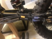
Yeah exactly! I did this on my stealth bomber clone build. The phase wires run individual beside the swingarm with no heat shrink connecting all three, so they all have airflow individually.

81CBFF9D-DE9D-49B1-A917-4EAB54715AF9.jpeg


Similarly, conductors running through conduit or other enclosed path have a reduced capability for the same reason. Running several fat conductors through a small metal is the worst of both worlds.
I've seen forum threads on the benefits of using fatter conductors outside of the motor to wick away heat. I've wondered how beneficial that might be, even with a little skepticism.

Yeah this method definitely works as it gave me cooler temps with my mxus 3k hub motor.

Then when I got my big soldering iron for soldering big connectors, I realized how fat copper wires not only conduct more current, but also how efficient they are at transmitting heat. You could put the iron on one end, and in no time the wire will be too hot to hold 6 inches away. Maybe a foot or so of 2 gauge jumper cable conductors just outside the motor would work as a good heat sink?
Well, with a mid drive, I think it would be beneficial to change the wires all the way to the coils/windings to lower IR. With hubmotors I did see benefit with changing wires all the way to the coils in my QS205 vs just adding the larger wires outside the axle. I think both methods work great for hub motors, it’s really about what you can fit through the axle.
 
A weller iron from home depot of the 180/240w dual wattage variety, plumbers iron, home depot or a good soldering iron, I doubt a 60w cheap iron would suffice on those conductor diameters.
The big phase wires and big winding wire requires lots of heat.
get underground heat shrink, double or triple it up.

Hammer tip for the soldering iron for what looks like 6-8awg wire. blow torch the wire could help the iron heat all those beefy wires up, but it may also add carbon, so its a delicate task.
14awg or 16awg solder diameter, as you need bigger diameter solder otherwise with the thinner solder you dump too much solder in, have to bring more, or shall we say unwind more solder out while in the middle of the doing the task at hand.

Setup and positioning and having the right tools is everything. Like a 3rd hand the rc guys use and a good solder iron stand that can be cheap, just tape the stand down when using it. Put on some big alligagator clips on the 3rd hand for the big wires. Love it.

Yeah, I would be crimping new phase wires to the coils, and would use a small torch to melt the old solder.
 
The nice thing about this styel of motor is that unlike a hubmotor you don't have to fit it all thru an axle, so you can go about as big as you want. You just have to increase the size of the hole in the outer case to fit that and any grommet/etc you use to keep the wires from pressing their insulation onto the casing.

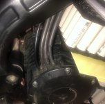
Yeah, upgrading these phase wires would be a lot easier than doing hub motors! Like you mentioned, probably just have to increase the hole size coming out of the case. 317B4656-5915-4E91-9E21-0F4C15F31AE5.jpeg
 
BTW, I meant to also add in my other post that you can do a test under max load to see if you even need to do a wire upgrade. Setup a voltmeter wired from the motor end of the cable (inside the motor if possible) to the controller end of the cable. 200VDC (and AC) setting should be sufficient, but use a cheap meter in case it isn't. ;) (2000vdc setting would work but won't show you useful data in this test).

Watch the meter during a run at highest load, and if you see any voltage on the reading, note that down. (no reading is good, means insufficient resistance to generate voltage across the cable). If the reading is very low, change the meter range down to match so you get a more precise reading.

Then you can multiply that voltage by the average current it would have been at that point (if your controller logs max phase amps you can use that). That gives you the watts lost in the cable.

Or divde the voltage by the current to get the approximate resistance. (ostrich (ohms) sees the vulture (volts) over the ants (amps)).


Unless the volts over the cable length is significant (more than a few millivolts) it's probably not worth the troulbe of replacing the wires.
 
Yeah this method definitely works as it gave me cooler temps with my mxus 3k hub motor.
Nice, been thinking about doing the same thing for my MXUS mainly for the chance at quicker heat dissipation - remember what gauge wires you were able to fit through the axle?
 
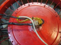
The biggest you can fit thru an unmodified MXUS3k is at or under 10g depending on insulation thickness (I tried before the axle broke there). To modify one of mine (450x, can't recall if it was a 4504 or 4503 or 4505), I used solid singlestrand 10g transformer wire (out of a dead harborfreight welder), that just has a coating on the wire, and some kapton and/or teflon tape "just in case", in slots cut in the axle (because the axle itself broke and the best way to fix it that didn't leave it weak included not leaving the diagonal hole in the axle), and just a little filed notch in the bearing ID...using two phases on one side and one phase plus sensor wires on the other.
dsc08102.jpg

Not my recommended method of upgrade, but if the axle is already messed up.... ;)
 
Well, with a mid drive, I think it would be beneficial to change the wires all the way to the coils/windings to lower IR. With hubmotors I did see benefit with changing wires all the way to the coils in my QS205 vs just adding the larger wires outside the axle. I think both methods work great for hub motors, it’s really about what you can fit through the axle.
Ya, I figured out it was a mid drive after seeing amberwolf's post. And it looks like a fairly easy task to enlarge the openings to squeeze in larger conductors.(y)
 
7 gauge is beefy, I saw 70h assumed big hub l.o.l.
I got cheesy c4k, didnt last long at all (always had issues, until the cast casing broke) but phases are physically small, 14 or so.
Googles got the 90H winding/phase connection on images.
phases go through the Hard plastic, maybe glass reinforced, with a good seal the way it is.
 
The biggest you can fit thru an unmodified MXUS3k is at or under 10g depending on insulation thickness (I tried before the axle broke there)
Hmm, did you happen to try all 3 phase in 8 gauge without insulation by chance? I have some insulation-stripped stranded 8 gauge wires I managed to find some high-temp thin PTFE shrink for that I'm hoping will fit through the axle, just haven't gotten around to trying it yet. Been procrastinating mainly because if it ain't broke... you know the rest.

8g_ptfe.jpg
 
Hmm, did you happen to try all 3 phase in 8 gauge without insulation by chance?
No, because the 10g was the biggest I had at the time. :)

(well, I also had some stuff the size of the entire axle end, but that definitely wouldn't fit thru there).


If I was really going to do a wire upgrade to something truly FAAAAT, ;) I'd do something proposed by John in CR years ago: change out the side cover for a custom-made one with a MUCH larger ID bbearingg, and make a ring with separate holes for the finger-sized phase wires and the grommets that will seal their entrance, and two other separate holes for a hall sensor bundle, and a thermal/etc sensor bundle.

This ring would fit between the bearing ID and the axle shoulder, and be attached (epoxy, threads on it's ID and axle shoulder OD, some form of mounting screw, etc) to the axle itself so ti cannot rotate relative to the stator.

It's tough to do this kind of mod on a motor that has to be driven by a chain or belt on one side and have a disc rotor on the other, but it would work fine on my SB Cruiser v1.x where the disc would be on the outboard side and the inboard side would be clear on both rear wheels. (the chain drive from the pedals would go to the front wheel, up and over the headtube/fork crown like the Trucktrike does. (wish I could buy the assembly from him). ) Then the phase wries would head right along the frame to the Lebowski/HondaIMA controller inches away on each side. :)

An even better version of that mod (for anything that can use a single-ended axle) would replace the entire inboard side cover and axle with a unit that has a giant bearing on the outside edge and a thin ring to support it that bolts to the motor cover bolt ring area. The stub axle would go on to the outside adn be threaded there for a spinner nut like 100-year-old cars sometimes had. The cover/axle unit would have plugs integraed into them that mated with plugs on the stator module so you can unplug and remove the entire motor/wheel just by slipping it off the axle once the nut is removed. Splines or keyways on the axle would mate with the stator support core to ensure fitting only one way on there to keep alignment easy.

Not that I'll ever be able to build any of that....but it'd be an easy strong way to deal with motor mounting and power delivery.

(a more practical version of that simply uses something liek the qsmotor single-sided hubs that use standard bolt on automotive wheels, but instead of using those wheels use a custom hub that a spoked wheel can be built on).
 
If I was really going to do a wire upgrade to something truly FAAAAT, ;) I'd do something proposed by John in CR years ago: change out the side cover for a custom-made one with a MUCH larger ID bbearingg, ...
Ha well I think going any further probably wouldn't be worth it with this motor (4T winding) and power levels. In any case, if I get even modest gains in the heat dissipation area with 8G wires and refresh the ferrofluid at the same time I'll be happy. At least I can still remain optimistic my custom 8G wires will fit, thanks for the feedback.
 
Yeah, if i were to do either of those hefty mods I'd be doing them to my QS205 motors (though I'd need a rotor / covers for one of them as it's just the stator).
 
Ha well I think going any further probably wouldn't be worth it with this motor (4T winding) and power levels. In any case, if I get even modest gains in the heat dissipation area with 8G wires and refresh the ferrofluid at the same time I'll be happy. At least I can still remain optimistic my custom 8G wires will fit, thanks for the feedback.
Why don’t you like the 4?
I have the 5T, love it 😍
Personally, I think it’s the best performance hub motor for a mountain bike frames, I like the QS205 better but it’s too heavy for a bicycle frame.
For the mxus 3K, I just added larger phase wires outside the axle. The 3K has a small axle so I didn’t bother with it. With my QS205’s I run larger wires through the axle, 6awg with the wires stripped and used a thin heat shrink for more clearance.
 
Personally, I think it’s the best performance hub motor for a mountain bike frames, I like the QS205 better but it’s too heavy for a bicycle frame.
No I think so too, 20 lbs is a pretty good arbitrary hub motor weight limit for mountain bike frames.

I like the 4T, it's more that additional battery current and phase amps doesn't really appear to develop more torque above a certain speed (~20 mph for my setup) unlike like with the 3T winding, at least according to the motor simulator.

If I understand it correctly the 4T winding saturates too quickly for additional power at moderate speeds. I'm running about 130 phase amps and going higher wouldn't give me much except a slightly higher boost off the line. In the end I think I would've been a little happier with the 3T winding, but that's OK. At this point a phase wire upgrade for a minor improvement to overall efficiency-->range is probably my last upgrade for this bike build.
 
Hummina Shadeeba off topic I joined today when I noticed your conversation from 2020 on magnets and motors and the pushback you recieved. Are you still interested? Looking for collaboration? If so do you have a place where your able to communicate public or private to exchange some ideas?
 
Hummina Shadeeba off topic I joined today when I noticed your conversation from 2020 on magnets and motors and the pushback you recieved. Are you still interested? Looking for collaboration? If so do you have a place where your able to communicate public or private to exchange some ideas?
Don’t know what ur talking about but u can message me here
 
Back
Top