Recumbant Mid-Drive Scrapbuilt Buildlog. Pics & Questions.

Progress:

EVB%20031.jpg


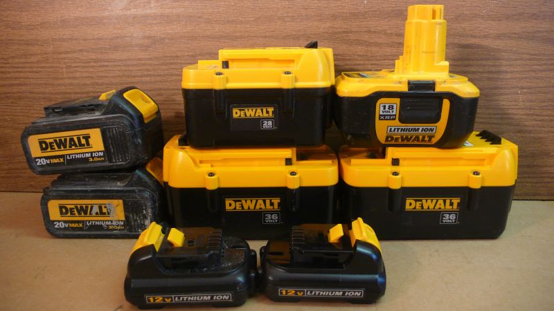
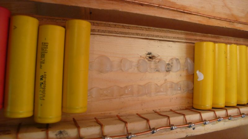
Out of each pack, 1 or 2 cells dead. 70% working just fine overall.

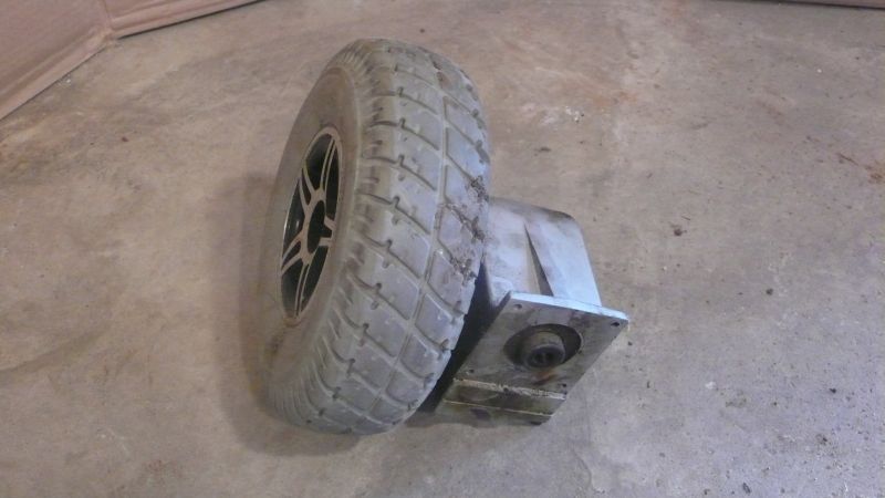
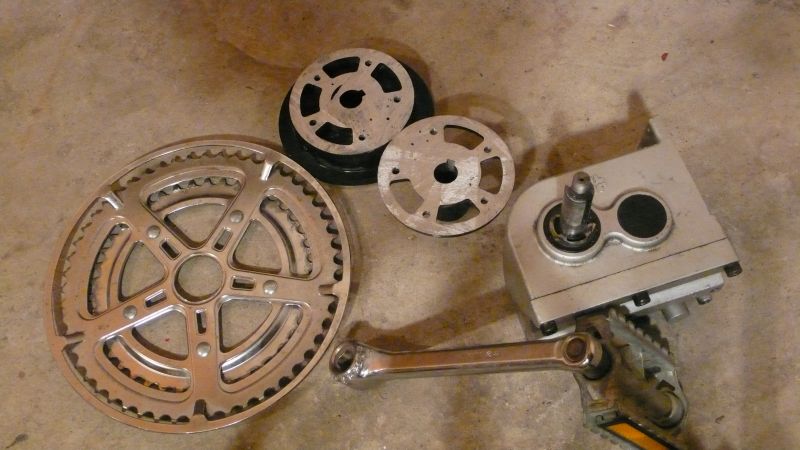
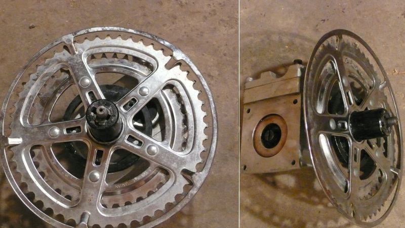
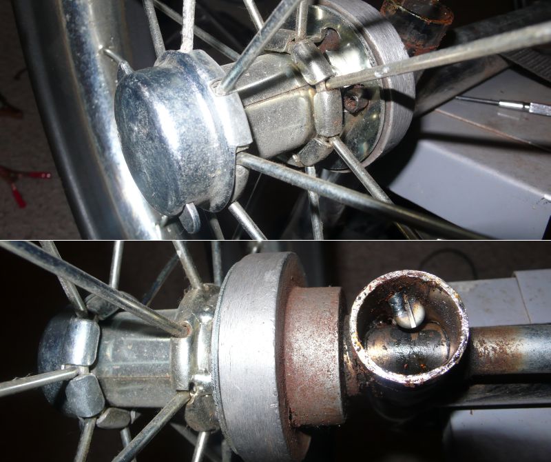
Then on an old powered golf caddy I found some freewheels, (the rusting things):

EVB%20032.jpg


And pulled off they look like so:

EVB%20033.jpg


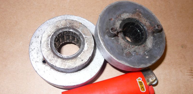
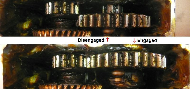
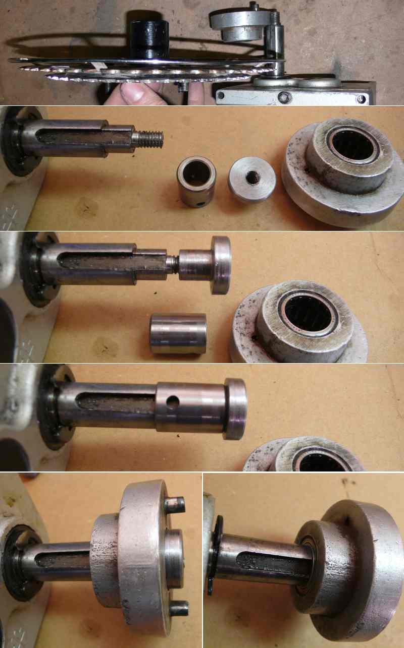
These are overrunning clutches, not pawl-type or ratcheting. Completely silent when coasting.

EVB%20034.jpg


These were gifted to me, someone bought them off Ebay and ended up not using them. Not sure if LiCo or LiFe. I suspect LiCo.

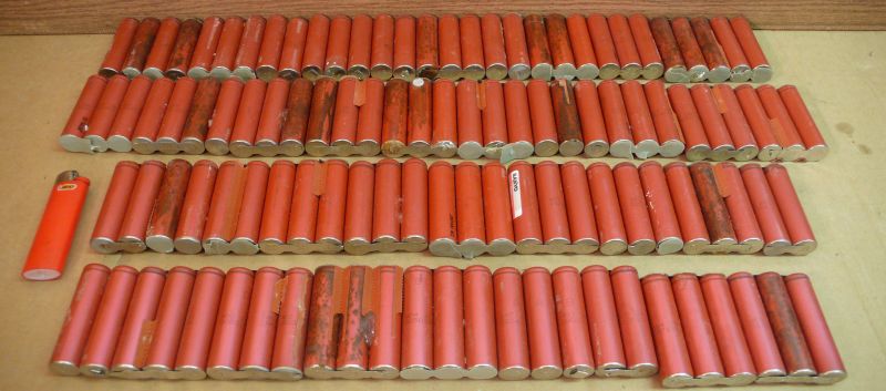
A word of caution about Ebay buys of extracted batteries. Out of the box, 34 chargeable, 78 dead and gone. 30% success rate. (Compared to 70% from disassembling packs I rescued myself). These packs have clearly been picked through already, likely by the sellers, and the ones on top were, by far, the more often working ones than lower down. I suspect they threw in a few questionable ones and padded the bottom of the box with ones they knew were dead (visibly leaking electrolyte or chained to ones that were). So, buyer beware. You'd be better off buying packs not disassembled yet so you can be the lion rather than the jackal.

Batteries were all 3V+ or under 0.1V anyway, so that made Keep vs. Scrap easy.

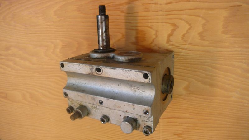
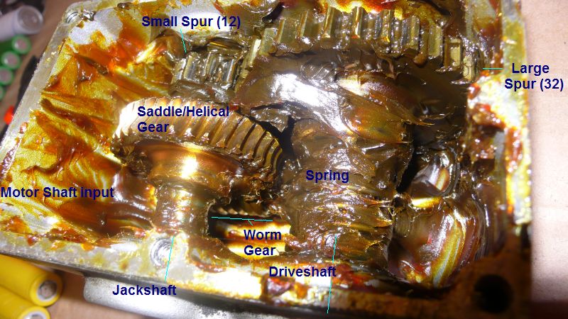
For my gearbox I found possibly a better option. An acquaintance repairs powered wheelchairs and said I could have a dead motor/gearbox. They are 90 degree, and have geardown. He said I could have one with a working motor (24V) but I asked for one with a blown motor since I already have a motor.

Also made contacts with people at an EV shop who're looking to hook me up with some old stock, or things they don't want to repair.

Things are looking up.
 
Been slacking on this while waiting for parts for a month. But, progress is being made.

Built a massive parallel charger for the 18650-sized cells.

EVB%20035.jpg


And picked up another load of "Dead" batteries. Still about 70% recoverable:

EVB%20036.jpg


And then the motherscore. Had a contact hook me up with some "dead" LiPo packs and their BMSs:

EVB%20037.jpg


65 pounds worth of LiPo. $5000 worth of cells, if new and functional. Which is somewhere around 4000Wh. Which is somewhere around 1000km (600mile) range at 25km/h (15mph) with no pedaling.

A few issues:

1 - I presume for them to be "dead" that some cells are overdischarged and gone. But they're stuck together with adhesive powerful enough that I think I'll tear (or at least bend) the bags if I try to actually remove the dead cells. So, I'll probably just disconnect them and haul their carcasses around.

2 - Cells are maybe not all matched, and with cells so large this actually matters (8 in parallel at a time averages out, 1 does not). Many of these cells seem similar, but I might find myself limited to the capacity of the smallest cell.

3 - LiPos are fragile.

4 - Charging might be an issue now, I might have to build a gigantic switchmode power supply to regulate current.

5 - I don't know how to configure the BMS in each of them, so that they'll cooperate with each other (multiple BMSs in.. series I guess).

I'd hoped to be riding back in April already, but, feature creep is having me lean towards building a better bike later than a crappy bike sooner.
 
MattsAwesomeStuff said:
Built a massive parallel charger for the 18650-sized cells.
Just beware of it not actually contacting all the ends at the same time. If you use enough clamping force, fully parallel along the wood, it should "indent" the wood wherever some cells stick up a teeny bit more than others and then get them all connected properly. I ran into problems trying to do the same thing using only two inflexible metal bars, where the cells didn't all make contact properly at both ends, as they are not all exactly identical (even the ones from the same manufacturer), sometimes because of torn-off tab welds and such.


1 - I presume for them to be "dead" that some cells are overdischarged and gone. But they're stuck together with adhesive powerful enough that I think I'll tear (or at least bend) the bags if I try to actually remove the dead cells. So, I'll probably just disconnect them and haul their carcasses around.
Denatured alcohol (or even isopropyl) will usually at least temporarily "deactivate" many adhesives, and usually permanently remove them. Just test to be sure it won't damage the cell casings first. (almost certainly will not, but check...).

Outside or in a well-ventilated area, put DA in a bowl or container big enough to partially immerse the pack in, and let it soak a few minutes, then try a plastic shim (about like a credit card but with no stamped-raised stuff on it) to slowly insert into the gaps between cells. Once a gap is enlarged a little, re-immerse the pack and soak, and keep repeating till it's all done. Alternately just use something to apply the DA to the adhesive areas/gaps and enlarge with the card, if you don't have a container large enough for the pack.


2 - Cells are maybe not all matched, and with cells so large this actually matters (8 in parallel at a time averages out, 1 does not). Many of these cells seem similar, but I might find myself limited to the capacity of the smallest cell.
You could test them once assembled into groups, under load, and see which groups of parallel cells have more voltage drop or run empty faster. Mark each group with this info, and then build a pack with the best groups. The other groups you then troubleshoot with a binary search to find and remove the problem cells, and repair with any spare cells.


3 - LiPos are fragile.
If by "LiPo" you mean "pouch cell", then yes, they often are. But remember that LiPo doesn't specifically mean that type of cell. ;)

4 - Charging might be an issue now, I might have to build a gigantic switchmode power supply to regulate current.
Look around for old lab power supplies; usually adjustable voltage and adjustable current. FInd one that will handle all the current you need, evne if it's voltage is not high enough. Find other power supplies (with isolated outputs) that can also supply at least the max current you want, even if they have no current limiting, and can do it at at least (or more) the difference in voltage between what you want the pack to charge to and the lab PSU's max voltage. Then series all the PSUs, and use the lab PSU to adjust the final total voltage, and the max current limit.


5 - I don't know how to configure the BMS in each of them, so that they'll cooperate with each other (multiple BMSs in.. series I guess).
Maybe, but you might need diodes for that. There are several discussions from the last few weeks about that; sorry I don't have a link. Might be a wiki article with the links.
http://endless-sphere.com/w
 
Just beware of it not actually contacting all the ends at the same time. [...] as they are not all exactly identical

*takes a better photo*

EVB%20038.jpg


Not a problem. There's at least 1/8" of compression from each, and I clamp the whole top bar anyway.

Mark each group with this info, and then build a pack with the best groups.

This was the plan when I was using many LiFe cells and had extras and an infinite supply of them. But my supply of LiPo pouches is probably, at least for the foreseeable future, limited to what I already have. So, "extras" might be hard to come by. No matter, I'll have to make do.

Look around for old lab power supplies; usually adjustable voltage and adjustable current.

I have enough electronic knowledge to build my own power supplies, for free, from dead appliances and such. At least, pegging a constant voltage anyway. But adjustable current requires actual dynamic electronic control and isn't easy to build.

The bigger problem is that my LiPo pack might be as large as 4000 Wh. The fastest I can drain a home circuit is at 1800W, so that's ~2.5 hours to charge if I'm flatlining the breaker. Charging at home, overnight, whatever is a trivial task for me. But charging on the road while making rest stops isn't as easy. An 1800W charger would weigh ~20-40 pounds.

Versus, if I was using LiFe batteries, you don't need to bother with current control on the charge cycle, I carry a power cord with a built in rectifier and smoothing cap, and a big run cap in series to limit current and I'm done. No transformer, no regulator, just right out of the wall at 120vac --> 170vdc.

Good news: Of the first 43 cells I tested, 42 of them seem in perfect condition. I'm not even sure how these got reported as "dead", even cells marked as dead show identical voltage to the others. *shrugs*. Maybe the BMS left on them for weeks/months slowly revived the dead cells.

Maybe, but you might need diodes for that. There are several discussions from the last few weeks about that

Ahh crap. I've ignored the forums for the last couple weeks since I had nothing to contribute. I'll dig around.
 
Picked up the powrechair gearbox today.

EVB%20039.jpg


I pounded the wheel off, am left with a keyed shaft, and a 32:1, 90 degree all-in-one gearbox.

EVB%20040.jpg


Note it also has that other shaft protrusion on the bottom left there. That is a shaft that bends like a hockey stick about an inch into it. I know it's supposed to have a manual freewheel engage/disengage so you can push it without cranking the motor. I'm not sure how it works, if you pull on it or twist it. I would definitely like to use it though, to disengage the motor when batteries are dead (4000Wh and 1000km range at 25km/h probably never, but..).

Anyone familiar with powerchairs?

Other feature: Where the output shaft (long one) comes out, next to it is another rubber plug thing. The opposite side also has this pair, (with both plugged). So 4 options total. I presume both sides is to make the gearbox flippable to the other wheel. But what is the 2nd plug on each side for? The box is literally packed with grease so I can't see anything, would rather not scoop it out without reason. Is it likely to be a two stage geardown and the other position is for using only one set of the geardown?

At full open throttle I'm at 4200 RPM (170V) off the motor, so, at 32:1 geardown, that's 131.25 rpm on the drive sprocket.

Ideally, I want 200-600 RPM on the rear wheel using the rear sprockets (25-75km/h, 15-45 mph).

So, I should have a drive sprocket that is a ~50% bigger than the largest rear sprocket and it should all match up. Except this is stupid, I'm gearing down to 131 and then gearing back up almost 5x for high speed. Would make more sense to remove one stage of the gearbox, same problem as before.

But, it's at least doable, since I don't have to contend with the extra 2:1 geardown from the prop gearbox. I have chainrings of the appropriate size. If I go 32:1 down and then back up, so be it.
 
MattsAwesomeStuff said:
Note it also has that other shaft protrusion on the bottom left there. That is a shaft that bends like a hockey stick about an inch into it. I know it's supposed to have a manual freewheel engage/disengage so you can push it without cranking the motor. I'm not sure how it works, if you pull on it or twist it.

Tha'ts the clutch. Most of them twist. If it has a lockingpin hole in it, just stick a screwdriver or allen wrench in there, and turn it, usually 90 degrees. Sometimes you have to "rock" the output shaft a bit to engage or disengage it.

I used the clutch frequently on CrazyBike2 when I had the "350W" motor on there, but when I switched to the "650W" motor, it's gearbox did not have a clutch. :( So I could not rol the bike backwards hardly at all.


Other feature: Where the output shaft (long one) comes out, next to it is another rubber plug thing. The opposite side also has this pair, (with both plugged). So 4 options total. I presume both sides is to make the gearbox flippable to the other wheel. But what is the 2nd plug on each side for?
AFAIK it's to access a bearing for installation/removal. Most of these gearbox cases seem to be flippable, but the parts inside may not all be--some seem to be made specifically for left or right operation. Even the lid can be used either way--you just drill out the other "cap" for the clutch rod and cap off the first..


Except this is stupid, I'm gearing down to 131 and then gearing back up almost 5x for high speed.
That's what I did on CrazyBike2; the only issue I had was the massive torque capability at the low speed, which could and did destroy about any bike parts that were misaligned, espeically since it had the power to twist the frame. :(

It was quite simple to do it this wya, and was the primary motivator for using it liek that.

To mount the sprocket, I just welded it to the wheel's ex-hub, making it easy to mount to the output shaft. I also used a bolt-on version at some point.


You'll want to install some bolts in the "top" row of holes, too--without them the lid isn't perfectly attached and will probably leak. Some of these lids are also dirlled all the way thru on the meiddle row of holes, and can leak there if they aren't filled, ieven if not used.
 
Scooped out the grease for a look-see.

EVB%20041.jpg


1 - From the motor coupler shaft, a loosely toothed worm gear.
2 - A saddle/helical cut gear on a jackshaft, meshing with the worm gear at 90 degrees (not sure of tooth count, but 12x).
3 - A small (12) spur gear on the same jackshaft.
4 - A large (32) spur gear on the drive/wheel shaft.
5 - A spring on the driveshaft to hold the large spur at the edge of the box so that it connects to the small spur gear.
6 - A hockey-stick lever that can shove the large spur gear so that it compresses the spring and disengages from the small spur, when twisted from outside the case. (Amberwolf was right)

EVB%20042.jpg


Notes:

A - The freewheeling action is best for when you want to disengage the motor from turning the wheels, not the reverse. While either way holds the gears apart, if the wheels are moving it will scrape the lever against the large spur as it rotates, whereas with the reverse, the small spur rotates freely in the air with no scraping. (Crappy for me, I want the reverse, so I can pedal when the batteries are dead without cranking over the motor).

B - There's no such thing as moving the driveshaft up to the jackshaft, at least not without changing everything else out. The large pinion is incompatible with the worm. The shafts themselves are different sizes (drive shaft is larger). The rubber plugs are just there to serve as end caps.

C - Unlike most worm gears (like the one Amberwolf mentions that couldn't go backwards) this one does not lock up when the helical gear tries to turn the worm. The angle is sufficiently steep that they mesh without locking. But it's not easy.

D - Overall geardown is 32:1. Most of the geardown occurs on the worm (12x) stage. The remaining (32:12 or ~2.66x) is in the spurs.


32:1 isn't great but is workable. 12:1 total is ideal for me. In a perfect world I would use the jackshaft as my output shaft and skip the spur pair altogether (since the freewheel is only emergency-usable in reverse anyway). But it's cut off flush. So, I need to gear back down by ~50%. I'll muck around with it a bit more before deciding.

I'd need a 48 tooth gear on the drive sprocket, which is fine, that's a normal big chainring. It'll taco the chainring if I don't bring it up to speed before engaging it though, even on the small gear. Which interferes with my "Screw speed control, just use a relay" plan.

That's what I did on CrazyBike2; the only issue I had was the massive torque capability at the low speed, which could and did destroy about any bike parts that were misaligned, espeically since it had the power to twist the frame.

On 650w eh? Hrm. Mine'll be capable of, oh 2500 for sure, probably surges to 3x that if it tried to lock up. It'll definitely mash the gear first and the whole frame immediately afterwards. Sounds like I'll be pedaling all my starts for a while.

To mount the sprocket, I just welded it to the wheel's ex-hub, making it easy to mount to the output shaft. I also used a bolt-on version at some point.

AHA! One of my last few "I'm sure I could figure this out, but don't have any ideas yet" obstacles. I'll be doing that. Thanks.

You'll want to install some bolts in the "top" row of holes, too--

Was wondering if that was necessary. They're not throughholes, but, I'll put bolts in them anyway I think. This should help with mounting/rigidity.
 
MattsAwesomeStuff said:
Scooped out the grease for a look-see.
You can also see the insides of another type over at my http://electricle.blogspot.com if you're interested enough to find the post with the pics. But I dont' remember the title of the post or exactly when it was. Should be tagged with motor or something like that.


A - The freewheeling action is best for when you want to disengage the motor from turning the wheels, not the reverse. While either way holds the gears apart, if the wheels are moving it will scrape the lever against the large spur as it rotates, whereas with the reverse, the small spur rotates freely in the air with no scraping. (Crappy for me, I want the reverse, so I can pedal when the batteries are dead without cranking over the motor).
The clutch is actually designed for "freewheeling" the output shaft, so that a helper can push the chair around without overcoming the motor and gearbox reduction drag (which is quite a lot).

So it can do what you want, but there will still be drag on the system.

What would be better is to use a freewheel on the output shaft of the motor. Take the threaded part of an old rear bike hub or a threaded bottom bracket cup, and weld *that* to the ex-wheel hub, and thread a freewheel onto that. Then just use the motor in the direction that allows the freewheel to drive from the motor but just spin with the pedals.


C - Unlike most worm gears (like the one Amberwolf mentions that couldn't go backwards) this one does not lock up when the helical gear tries to turn the worm. The angle is sufficiently steep that they mesh without locking. But it's not easy.
Oh, locking up the helical wasn't the problem--just that the force necessary to reverse turn the motor via the reduction gearing thru all the bike's gearing too was so high that it was beyond hard to move the bike backwards--just barely possible, but so so hard I didn't bother unless I absolutely had to.


I'd need a 48 tooth gear on the drive sprocket, which is fine, that's a normal big chainring. It'll taco the chainring if I don't bring it up to speed before engaging it though, even on the small gear. Which interferes with my "Screw speed control, just use a relay" plan.
I tacoed enough parts from misalignment to know it's easy to do...but if you have proper alignment of forces it should work ok.

On 650w eh? Hrm. Mine'll be capable of, oh 2500 for sure, probably surges to 3x that if it tried to lock up. It'll definitely mash the gear first and the whole frame immediately afterwards. Sounds like I'll be pedaling all my starts for a while.
Oh, no, I meant that it was a "650W rated" motor. I actually got quite a lot more than that, including at one point over 4KW burst, I think, when a chain derailed and tangled in the rear crank/chainring, pulled the wheel out of hte dropout and crushed it against the frame. :lol: Something like 150A at 36V, just before the controller blew the FETs. Carnage pics and details are on the old blog linked above.
 
You can also see the insides of another type over at my http://electricle.blogspot.com if you're interested enough to find the post with the pics. But I dont' remember the title of the post or exactly when it was.

Well, I went searching/reading for a couple hours. Interesting stuff but didn't find any disassembled pics of your gearbox.

So it can do what you want, but there will still be drag on the system.

Well, I'm no concerned with the drag as I am the abrasion wear (and the ensuing particulates) from the large spur gear scraping on the lever for miles on end. In a wheelchair scenario, it's meant for a little bit of walking only, not miles.

What would be better is to use a freewheel on the output shaft of the motor.

Yeah, but I was looking forward to the simplicity of it already being done. I have those two expensive overrunning clutches to use, but no way to replace them.

Oh, locking up the helical wasn't the problem--just that the force necessary to reverse turn the motor via the reduction gearing thru all the bike's gearing too was so high that it was beyond hard to move the bike backwards

Well, I can twist the shaft with my hand, so, throw a gear on there I should be able to move it even easier. I guess my angle is pretty slouch.

I tacoed enough parts from misalignment to know it's easy to do...but if you have proper alignment of forces it should work ok.

What kinds of things should I look out for, allignment-wise? Shouldn't matter if the gearbox isn't all that straight, I'm retaining the rear sprockets so the chain will have some angle. As long as the chainring is square to the gearbox I should be (hope I'm) okay.

Something like 150A at 36V, just before the controller blew the FETs.

Yow.

My halfass solution is a STDP switch to tie in a power resistor that limits current. I'll probably throw it on the left hand somewhere, hold it in to limit the current for the few seconds I'm accelerating from a stop. No reasonably-sized power resistor will withstand this for long, but, it won't need to.
 
MattsAwesomeStuff said:
Well, I went searching/reading for a couple hours. Interesting stuff but didn't find any disassembled pics of your gearbox.
Sorry....I know they're in there somewhere, but I never made an index like I'd planned to. :( Half the time when I need to find something in there I have to use google site search on a word or phrase I think I might've used. :lol:

Maybe using "grease" and "gearbox" or "powerchair motor" in a site search of my blog would find it. (note that even though they should work identically, the site search from google's homepage will find things that the on-blog "site search" will not. :? )


Well, I'm no concerned with the drag as I am the abrasion wear (and the ensuing particulates) from the large spur gear scraping on the lever for miles on end. In a wheelchair scenario, it's meant for a little bit of walking only, not miles.
Ah; I wonder if there is a fix for that. Perhaps a pin in the casing (outside if possible) that prevents the lever from flipping all the way over to the spur gear, yet still fully disengages the clutch?


What kinds of things should I look out for, allignment-wise? Shouldn't matter if the gearbox isn't all that straight, I'm retaining the rear sprockets so the chain will have some angle. As long as the chainring is square to the gearbox I should be (hope I'm) okay.
As long as the "top" of the chainline, where power is applied (vs the slack side, usually the bottom), is aligned side-to-side, so that it always rides straight from the top of the driven sprocket to the top of the driving one, and the teeth are always engaging only the center of the chain, never the sides, it should be ok.

The problem comes when the frame flexes from the torque pulling the chain so hard that the chainline shortens and then the chain can ride up on the sides of the teeth, and derail. This can even happen just with pedal power on a flexy enough frame, if you're seriously standing on the pedals cranking hard up a hill or something. Has happened to me on more than one cheap bike before my motorizing days, although at the time I didn't understand the mechanism behind the derailing, only that it happened under those conditions.


My halfass solution is a STDP switch to tie in a power resistor that limits current. I'll probably throw it on the left hand somewhere, hold it in to limit the current for the few seconds I'm accelerating from a stop. No reasonably-sized power resistor will withstand this for long, but, it won't need to.
I guess it's worth a try, but the switch will have to be able to withstand connection and disconnection under power, as well as handling the peak and continous power, at or beyond the voltage you will be running at. You don't want the switch contacts to weld. Easier to find the resistor than the switch. For the resistor you could even wind a bunch of wire around an insulator, until you have the right resistance to lower the current. Be a lot of wire, though. ;) If you don't care abotu the inductance of it, you could use motor wire or magnet wire, and wind it aorund the bare metal bike frame tubing very tightly, to help it dissipate the heat. (then paint over the whole area to prevent rust).
 
Ah; I wonder if there is a fix for that. Perhaps a pin in the casing (outside if possible) that prevents the lever from flipping all the way over to the spur gear, yet still fully disengages the clutch?

Hrm. One of three things: I'm misunderstanding you, I'm misunderstanding how the mechanism works, or you're misunderstanding how the mechanism works.

The lever is bent. When you rotate it, the bottom part swings out and makes contact with the spur gear, which is held where it is by a spring. If you keep twisting the lever, the bent part shoves the gear back, compressing the spring mounted on the shaft. This eventually moves it far enough to disengage from the other spur.

If at any time the lever is removed, the spring shoves the gear back to the end of its travel, re-engaging it.

So, the lever has to remain in contact (with moderate pressure too) of the large spur gear. If that gear rotates, it will scrape along the lever.

So, I don't understand where a pin could go.

As long as the "top" of the chainline, where power is applied (vs the slack side, usually the bottom), is aligned side-to-side, so that it always rides straight from the top of the driven sprocket to the top of the driving one, and the teeth are always engaging only the center of the chain, never the sides, it should be ok.

What about using the rear sprockets? Suppose I have a stack of 6 on the rear tire and only a single chainring, will that much angle be a problem? I was hoping to center the chainring so the chain is angled at most 3 chain widths left or right. Doable or stupid?

I guess it's worth a try, but the switch will have to be able to withstand connection and disconnection under power, as well as handling the peak and continous power, at or beyond the voltage you will be running at. You don't want the switch contacts to weld. Easier to find the resistor than the switch.

Well, I'm not going the normal route, with 12-36V motors and high amps. I'm using 170V and lower (relative) amps, around 15. That's normal household voltages and currents, so, any of the relays from household stuff should be fine. That's one thing my design has it easier than others.
 
Another month, another lack of progress. Bit the bullet and got to work tonight.

Some progress:

EVB%20043.jpg


Up top is the old wheelchair wheel hub (thanks again Amberwolf for the fantastic suggestion to re-use it!). I need to fit two things on that shaft, so I spent a half hour hacksawing an inch off the outside so only 1/4" is left. I'll trim the other side later.

I also drilled around the old crank, dremeled, chiseled, until I got the chainrings off the crank. A bunch of filing and it fits onto the wheelchair hub.

Bonus, both are 5-spoked and the holes line up perfectly.

EVB%20044.jpg


And they fit nicely back on the gearbox.

Bolting is nice because if I pretzel up the chainrings or go with a different motor or want to gear it for different speeds later, I can just unbolt it again.

Next, I have to mount one of my overrunning clutches to the same shaft. One would require the shaft to be built up, the other lathed down. Annoyingly, the difference is enough that it would bite into the shaft key, so that makes things a bit complicated.

Sort of a milestone, it's the first time any parts have been assembled together since I started the teardown.

Oh, and I also met Justin Le in person at Vancouver Makerfaire and got some ideas from him. That's neat, to put faces to posts.
 
Minor update. Got the driveline temporarily assembled with some poorly rigged couplers. No particular reason or benefit in doing so. The project has stalled for me and I wanted that motivation boost of seeing something move so I connected A --> B --> C.

Unlisted video for those curious: http://www.youtube.com/watch?v=a24e3bFdc6Q

So, what you see there is the treadmill motor on the left, an ugly coupler, the 90-degree (and 32:1 dual-stage geardown) wheelchair gearbox, and a 1/4" thick sawed-off slice of the original wheel hub bolted to an old pair of chainrings.

6v on the motor (will be 120-170v with the full pack) and the chainring rotates.

Having a bit of trouble figuring out actual mechanical couplers and coming up with a way to mount the motor to the gearbox without it hinging or wobbling. And then somehow fitting that into the bike frame.

Another challenge is how to fit a traveling pin overrunning clutch (1-way freewheel) to the output shaft beside the big chainrings. The shaft on the gearbox is too narrow but only slightly (0.080" total, not enough thickness to use a shaft key), yet it needs to withstand the pressure of me pedaling.

The driveline is holding up progress on the rest of the bike, 'cause everything has to be built and planned around fitting it in. Hence, putting stuff together just to re-motivate.
 
The upper picture is how things started. The old hub and the sprocket already fit on the shaft, but I needed to get the overrunning clutch onto there somehow. The shaft is too small for the clutch directly, but not by enough for a bare collar (0.080" total). Luckily, the place the clutch came from had a precisely machined and hardened collar of its own.

So, the shaft was lathed down, and then a custom nut/collar/cap was added to the end to lock it all in place. It could've been just a nut with no collar, but it was suggested I leave as much of the hub intact for torque reasons. So the nut serves as a 1/2" extension too.

EVB%20045.jpg

[Pics taken to show how pieces fit together, not the actual assembly sequence]

Next up, the nut head needed a couple flat spots ground in so I could get a wrench on there. Then, trimmed a 1/2" off the hub with the sprocket to make up for the part of the shaft that the freewheel stole.

This cap/collar/clutch assembly was the only discouraging "I don't know how and don't have the tools to do this" obstacle in the build, far as I can tell.

...

Did a full speed test while it was temporarily coupled with hose. Is actually quite nice, I can bend it 10 degrees or so without it complaining.

[youtube]C9ORfSISFNc[/youtube]

Ta da.

The wobble is because I'm using round cup washers until I get some lock washers. The grinding noise is just my lens cap vibrating on the edge of the table.

The power supply is my Variac that I finally rigged up more permanently, threw in a 25w lightbulb for cap drain and a DPDT AC/DC rocker.

The traveling pin overrunning clutch freewheel is awesome and silent. No click-clack ratcheting.

Gearbox is actually dry from me disassembling it to take pics. Need to grease it back up.

Next up is to design a proper coupler and mount the gearbox directly to the motor frame so they can't wobble or hinge.
 
Another two weeks, some more progress.

Huge milestone! Driveline is functionally complete and assembled! Now, to build an actual bike around it.

[youtube]5XYJRf9O5xc[/youtube]

It seems like such a tiny amount of progress for 2 weeks off/on work, but, when I detail it out I see where all the time went.

Progress:

- Cut 4 aluminum spacers from some manifold scrap, to fit between the motor and gearbox.
- Couldn't find any M6 capscrews longer than 2", needed 2.5". Drilled out the gearbox, tapped holes, and replaced with much beefier 5/16" bolts.
- Trimmed some studs off the inside of the motor end cap.
- Drilled (redrilled, drilled again) 4 mounting holes in the motor end cap.
- Discovered the bolt heads interfere with where the end cap mounts to the motor shell cylinder, ground 4 clearance slots.
- Ground down a shaft to fit the gearbox input slot, split a pipe to fit around both, slid both of those inside another pipe, JB welded it together.
- Trimmed the gearbox coupler and the motor shaft to fit inside the room left by the alum spacers, plus a tiny gap (for misalignment flexibility).
- Bought and trimmed some 5/8" fiber-reinforced hose as a coupler.
- Made a hoseclamp tool (turns any scrap wire into a custom hoseclamp in seconds), used it twice to clamp the hose to the two shafts.
- Replaced cup washers on the big chainring with proper washers & lockwashers.
- Removed temp chainring from kids bike (the black sprocket).
- Drilled temp chainring for temp mount to freewheel.
- Filed the inside of the temp chainring to clear the custom nut.
- Bolted it all together, reassembled the motor.
- Knocked it off the bench, bent the chainguard but thankfully not the actual sprockets.

The motor/gearbox/freewheel/chainring assembly weighs 28 pounds. Not bad for being rated at 3.5hp continuous without even being in airflow.

The largest challenge remaining now is figuring out how to mount it to the frame, especially figuring out how to rig the rear suspension (which has to go right onto the motor/gearbox probably).
 
If you look at my CrazyBike2's old powerchair drivetrain, you'll see that I spread the center frame stays out and welded a plate across them, then drilled slotted holes in the plate for the powerchair gearbox to bolt to with it's six mounting bolts, using large washers under the boltheads to the plate for extra friction so I could loosen them, adjust chain tension, then tighten them to keep it from slipping around.

So depending on what your bike's design is going to be, you could do the same thing.

Alternately, if your frame tubing is small enough diameter to fit into the powerchair gearbox lid's tubing indentation, you could use that plus a mounting plate off another gearbox to make a pinch-clamp, with six long bolts between them, and mount the whole thing on the downtube--but that would make a mess of the chainline unless it's the downtube of a rear frame that is then bolted or welded to the stays of a front frame you'd actually be riding on (similar to the way my CrazyBike2 has been built, or more like the way Dogman's FS Longtail is made).
 
If you look at my CrazyBike2's old powerchair drivetrain

Y'know, one thing you never did was amalgamate all your info in one place, in a concise but thorough way. I find all of your stuff quite interesting, and you and I line up very similarly in terms of "make it work", "do it cheap", and "be resourceful", but it's spread so far and so thin it's hard to find any specific thing. I wish I was around while you were building it, archiving is not so great on forums/blogs. Of course, doing this takes time and has little benefit, so, not being critical, just wishful thinking.

I spread the center frame stays out and welded a plate across them, then drilled slotted holes in the plate for the powerchair gearbox

Good to hear, that was my plan too. I hadn't thought of slotted holes. Thanks, I'll probably incorporate that.

Alternately, if your frame tubing is small enough diameter to fit into the powerchair gearbox lid's tubing indentation, you could use that plus a mounting plate off another gearbox to make a pinch-clamp, with six long bolts between them, and mount the whole thing on the downtube

I don't have multiple gearboxes, (wouldn't ruin one just for the lid anyway) but I can make a plate easy enough. The downtube will be behind the seat but it's on the wrong side. The gearbox cup has to face forward. I'm not sure if I'll even include the downtube at all or just create a mounting frame directly from the stays to the motor/gb assembly. The main tube will just be 1.5" box steel to the front fork.

I think I like the plate idea better though.

Thanks again for the feedback. Half the time you confirm my ideas as serviceable, the other half of the time you can tell me the better and easier way. :)
 
MattsAwesomeStuff said:
Y'know, one thing you never did was amalgamate all your info in one place, in a concise but thorough way. I find all of your stuff quite interesting, and you and I line up very similarly in terms of "make it work", "do it cheap", and "be resourceful", but it's spread so far and so thin it's hard to find any specific thing. I wish I was around while you were building it, archiving is not so great on forums/blogs. Of course, doing this takes time and has little benefit, so, not being critical, just wishful thinking.
I've had plans to do that for both the blog and the various build threads on ES, but it's just never high enough on the priority list. I actually started to build an index to the blog, when I started here on ES, but i never got very far and haven't gotten to do more or put it up.
 
Progress is slow. Getting demoralized 'cause I won't have it done before the frost line hits.

Made another rough sketch of where stuff has to go:

EVB%20046.jpg


And since then worked on fabricating a way to mount the gearbox (aluminum, no mounting points and not thick enough to tap) to the rear frame:

EVB%20047.jpg


The brackets will be JB Weld epoxied to the gearbox. I welded a mounting plate onto the chainstays that bolts through the mounting plate for the gearbox brackets.

I also cut, welded, and drilled the mounting plate for the pivots to attach to, and ground away a clearance hole for the clutch lever.

Around this time I noticed the mother of fails. Note the yellow arrow. The chainline does not clear the motor. In the small chainring and smallest casette it clears barely, but nothing clears on the big chainring and only a few gears clear on the small one. That means I'll need to have a power-side redirection pulley/sprocket right next to the chainrings. ARG. Unnecessary stupidity.

Next up is mounting the pivot to the gearbox plate (it needs to mount right inside the clutch lever, wonderful)... and figuring out mounting arrangements for the top and middle of the motor to the old seat stays.
 
you may be able to simply use a plastic tube over the chain to redirect it around the motor. Attach the tube to the side of the motor so it doesn't drive around. HDPE or similar should work well, and it will probably be quieter than a sprocket to do it. It's common enough on various recumbents.
 
you may be able to simply use a plastic tube over the chain to redirect it around the motor.

Even on the power side of the chain?

It's a fairly significant redirection, short range. But, plastic's cheap, I'll look into it, thanks.
 
I'm not sure; I only know that was a solution I was told to use to get my powerside around a battery box hose clamp; I did try it with some plastic sheet (HDPE? Nylon? I forget) that used to be part of a disposable 'clipstrip" for products to hang on in retail store aisles. it did work. A tube would have been better, but I didn't want to break the chain to put it on, so....

The one issue I had was that it was such a large redirection and so close to the cranks that somtimes it caused the chain to jump the sprocket on the cranks.
 
Peculiar. I would figure that a chain bending 20-30 degrees and sliding around a piece of plastic would simply saw through it like a chainsaw.

I'll give it a go.
 
Another month, minor progress.

Was gone for a few weeks, so, not too disheartened at the lack of progress.

Did a quick mock-up assembly (everything's hovering in place, not mounted).

- Created a ridiculously overbuilt bracket for the hinge. It has a cave for the clutch bar 'cause it had to be mounted right over top it.
- Drilled temp mounting holes for that bracket and the plate it mounts to before mounting to the gearbox. I'll weld the two plates together once I've sat on it and determined if I mis-thought anything.
- Stole the rear suspension off my new (to me) mountain bike, swapped it with the original one from the kids bike (it's much larger, longer travel, heavier duty).
- Bent and reformed an old chrome fender to fit the front wheel.
- Chopped the front wheel, head tube, & handlebars from the rear pivot. Front wheel and head tube will get re-used, handlebars will be replaced, sourced some conduit for that.
- Test fitted the rear suspension. Pivot is set, the rest of it not sure. Most of the top of the red/white frame will get chopped flat to fit the reclined seat.

EVB%20048.jpg


Looks okay except for the questionmark of my head tube angle and handlebar design. I'm going to try these instructions:

http://bikesmithdesign.com/Design/12Steps.html <-- This, and...
http://bikesmithdesign.com/EvoBars/EvoBarSetup.html <-- That.

Except that's all data for a LWB and I'm not sure how to adapt it to an SWB. But much of the advice is quite solid in terms of ergonomics.

Boring technical stuff:
------
The other problem is that the rear suspension mounts a bit high. Swapping the suspension from the kids (fitted to the red/white bike) to the adult size one means now the geometry's changed. The distance between the pivot and the motor-side mount is correct for the big spring (based on its donor bike), but that would yield a very shallow angle because the upper frame mount is sized for a spring 2" shorter and weaker. Angle should be close to 90' (pivot-to-motormount be 90' from motormount-to-upper frame), so that movement on the back translates directly into compression. It's like 60' in the picture.

My solution is to drop the motor mount almost to the bottom of the motor (where it should be for the old spring). That will keep the angle closer to 90'... but now leverage has changed. Spring will appear much softer if closer to the pivot? Ehn, it'll be what it'll be. I'll can fab the upper frame mount wherever, but any higher up and it forces me to place the seat higher, so it will probably stay.

In the end, I've basically swapped out the kids spring with an adult one, it's stronger and has much more travel. But I didn't put it appropriately far out, only slightly farther out than the kid's geometry. So net change is that it will have more travel than the kids one, but will be softer than what's expected on an adult one?

Is any of this stupid for reasons I haven't considered? I can't actually test any of this, "try and see" until most of the bike is set in stone (or, in weld). Fingers-crossed engineering :(
-------

Next, bolting it together. Got the rear suspension bolted onto the motor and one pair of seat stays as well.

EVB%20049.jpg

(you can also see the little cave for the clutch lever in the bottom left).

Progress/Notes:

- Cut extension strip for the rear suspension mount. So I'd have room to bolt it.
- Welded strip to the old red mount. Accidentally decent welds.
- Drilled mounting holes in the mount, drilled mounting holes in the motor, tapped holes in the motor, bolted (5/16") mounting plate to the motor.
- Tested the suspension. It suspends. Great.

- Drilled & tapped holes for 1/4" bolts on motor bottom sides.
- Bent seat stays to bottom sides of motor (to take the load from the suspension rather than the motor-gearbox joint taking it).
- Realized seat stays aren't long enough to reach said holes after bending.
- Decided to fab rear C-cup half strap and weld that to seat stays to cup the whole motor and then bolt those.
- Fabbed, bent and tack welded said strapping.
- Tried to disassemble motor, oops, strapping went under the motor cap bar (has to). So I have to disassemble the entire motor to get it on or off. NOPE. Cut those welds, threw strap away.
- Refabbed some 2" long 3/16" cups instead, unjoined, bent to curve, welded (horribly, back to normal) to seat stays.
- Ground flat, drilled 1/4" holes in seat stays.
- Bolted motor bottom to seat stays.... sheared a head off a stainless 1/4" bolt. Whoops. Ground the protruding bit's sides flat and wrenched the carcass out, replaced with spare.

- Considering replacing 1/4" bolts with 5/16" on those seat stays.
- Abandoned plan of mounting motor top to the 2nd pair of seat stays, since the brakes line won't clear the motor. Have to mount it higher (on the aluminum cap?) or think of something else. Biggest remaining obstacle.
- Wish I had some disc brakes instead.
- Grabbed two more donor bikes just in case.
- Considering scrapping the gearbox mount and starting over. It's poorly designed. Considering not even JBwelding it just hoseclamping it until it breaks on a test ride or two.
- Starting to get twitchy trying to figure out head tube angles and handlebar stuff, but, cross-that-bridge and all that, trying to ignore it.

Hopefully put some more time into it this week.
 
Back
Top