shorted motor windings?

m3vuv

100 W
Joined
Nov 16, 2017
Messages
222
Location
horncastle lincs uk
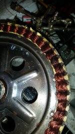
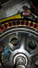
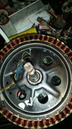
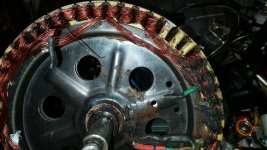
Hi all i have a 1kw direct drive hub motor,its been fine ,some time ago i was running it at about 3kw,did about 1000 miles then went to a smaller battery 47v+ 500 watt controller,been ok for about a year in that setup,the other week i got off the bike and pushed it down the kerb so jolted it a bit,when i tried to ride away after that it just made a sort of feint duzz from the wheel and wouldnt go,i stripped the motor,2 coils next to eachother look blackish,i also tested the resistance between phases and got about .5 ohm,then mounted the wheel in a vice and rotated it while measuring outputs between the phases,they all seemed about even,i thought the motor was ok so brought a new controller,fitted it with no change,just heavy current draw and a sort of buzz from the wheel,i am stumped,is this signs of shorted windings ?,also when it happened i had only ridden it slowly in town for about half a mile so didnt have chance to get warm,what else can i check,i am at a loss,cheers in advance m3vuv.Paul.
 
ive tried with and without the halls connected,ive swapped halls before and tried all combinations of connecting them,i have never had a case where the motor wont turn,they normaly turn rough and noisy and draw huge current in my experiance,this is not like a hall issue at all.
 
Have you tried generating some current?
Hook up a halogen light bulb between phases to see if one phase is really weak or shorted altogether.
That's all that I can think of right now. 🤔

I'm guessing you already looked at the wires where they exit the motor for any damage, short etc.
 
2 coils next to eachother look blackish,i also tested the resistance between phases and got about .5 ohm,then mounted the wheel in a vice and rotated it while measuring outputs between the phases,they all seemed about even,i thought the motor was ok so brought a new controller,fitted it with no change,just heavy current draw and a sort of buzz from the wheel,
A "stuck" motor usually requires swapping of two of the phase wires. The normal sequence when overheated is for the halls to fail, the magnets demagnetize, then the windings get cooked, and your winding seem to be partially cooked. However, since you're getting a normal resistance reading between phases, it seems like they are still OK, so the issue may have been the controller.

ive tried with and without the halls connected,ive swapped halls before and tried all combinations of connecting them,i have never had a case where the motor wont turn,they normaly turn rough and noisy and draw huge current in my experiance,this is not like a hall issue at all.
Can you confirm that this implies your controller is dual mode (sensored and sensorless)? If sensored, then I'd use the new controller (assuming the old one is faulty) and use the flow diagram in the link below to troubleshoot the hall and phase wires.

 
my phaes have continuety to the rim,is that ok?
Not OK. That's a bad sign. Do this test with the controller disconnected. There should be no continuity to the axle.
If there's a short in the phase windings, it's hard to measure since the resistance is so low. A short will cause the motor to be abnormally hard to spin with the wires disconnected.

You could try placing your meter on AC volts and measure across the phase wires while spinning the motor by hand. Measure each combinaton of phase wire pairs. See if one looks noticeably different.
 
the motor spins freely with the controller connected or disconnected,i did measure them with an avo8 they all look similar tbh.
that was measureing ac volts as the wheel was turned,the motor is a generic 1000w chineese direct drive hub motor,are the windings lots of wires in paralell wound on each pole ot just 1 wire?.
 
now its apart heres some pics 20230910_133930.jpg
 

Attachments

  • 20230910_133922.jpg
    20230910_133922.jpg
    2.3 MB · Views: 4
  • 20230910_133910.jpg
    20230910_133910.jpg
    2.9 MB · Views: 4
  • 20230910_133900.jpg
    20230910_133900.jpg
    2.8 MB · Views: 4
The next step would be to measure continuity to the stator. Does the wire insulation look good where it exits the axle?
 
If you have a LC meter, that would be a great test. Measure the inductance of each winding. Generally, there will be multiple wires in parallel on each winding.
 
thought so on both counts,my phase that draws most current seems to have 6or8 wires in parelell,thinking of feeding 12 at say 30a and see what gets warm,is that a good test?,i seeit as being that phase has an issue there may be nothing to loose?.
 
The next step would be to measure continuity to the stator. Does the wire insulation look good where it exits the axle?
yes ive already checheck the wires where they go thru the axle,that was my first port of call,a few hours ago when testing with it on the bike,i held the throttle max and connected one phase and it seemed ok,got to connecting my blue phase and it nearly blew my finger off,guess thats the one with issues!.
 
well some good news i think,i cut the wires on the shorted blue phase and unwound it to the point where the windings wet to another set of poles about 120 degrees to one side of the cooked windings,the end of the wires where i cut them are under the shrinkwrap in the pic(just to keep them together),if i now test for continuety between those wires under the shrinkwrap and the body of the motor i get no continuety,i think thats good,i also have continuety with those wires and the other phases so looking good i assume,i took off about 5 wires in total about 1m40 long,one turn is 9cm long so 1m40 x 3 poles at 9cm so the 3 poles=27cm of wire so 1m40 divided by 27= 5 turns,on the pic left to right the windings are cw-ccw-cw,does that seem right?.
 

Attachments

  • 20230911_000826.jpg
    20230911_000826.jpg
    3.1 MB · Views: 2
at the moment the windings are 0.2mm,using a cross section calculator it gives for 10 wires at .3mm as being total cross sectian as 0.706mm?,if i use 1.25mm wire with 6 wires it gives 7.36mm,is that ok to wind 6 turns of 5 lots of 1,25mm?,this is the calc i am using
does that make sense or am i way off,also why do they use multiple wires not fewer thicker ones,any special reason?,thanks Paul m3vuv.
 
It's not the enamel, it's about the air gap between strands that increases with thicker cooper. You might be able to fix the shorted spot with some heat resistant glue or something.
You want the exact number of turns and thickness of copper strands as there were before.
There will be someone who can explain better than me about why you don't want unbalanced phases.

You will have to rewind all phases if you use different copper thickness.
 
Last edited:
Back
Top