eMark said:
Won't that depend on the size of your pack and then choosing a controller with appropriate amp rating? You don't need to be pulled over for exceeding the legal speed limit (with not plans to get a license) :wink:
These bafang motors have a controller built in, supposedly all it takes is remove the bottom bracker slide in the motor, hook up the other stuff and add a battery but so far it hasn't been that straightforward.
Bought this bike and the motor thinking i'd be done after buying a battery pack that fits but it hasn't been that simple so far
The bottom bracket on my bike was completely stuck and couldn't be removed with normal tools, it went to a bike shop that got it out and said they never saw something like this in 30 years. After that the motor wouldn't slide through the hole because was slightly smaller then the normal diameter (probably a manufacturing issue) and had to have some shaved off for it to fit.
Next issue was that the 44t chainring was slightly to large and hitting the frame, put 3x 1mm spacers between the motor and the ring to clear it. the standard crank arms that came with the motor are not wide enough to clear the frame enough, i wanted to use the ones i had on the bike but didn't know the chainrings were non removable on the right arm (still looking for something that works)
Then onward to this battery issue!, couldn't find any per-made ones that fit
Honestly I'm going way over budget, estimations were 900~1100 euro, i'm heading towards 1500~1700 in the end i think
eMark said:
Here's another insightful article by spinningmagnets on frame triangle pack enclosures. Fabricating your own protective padded enclosure would be a worthwhile winter project ... https://www.electricbike.com/triangle-bags/
I'll go through it at some point today.
eMark said:
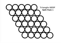
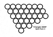
My grandson is in the process of deciding whether or not he wants to invest the time and money in a similar build as yours so it was by no means wasting my time planning out the following triangle configurations. In fact I enjoyed the mental exercise
")
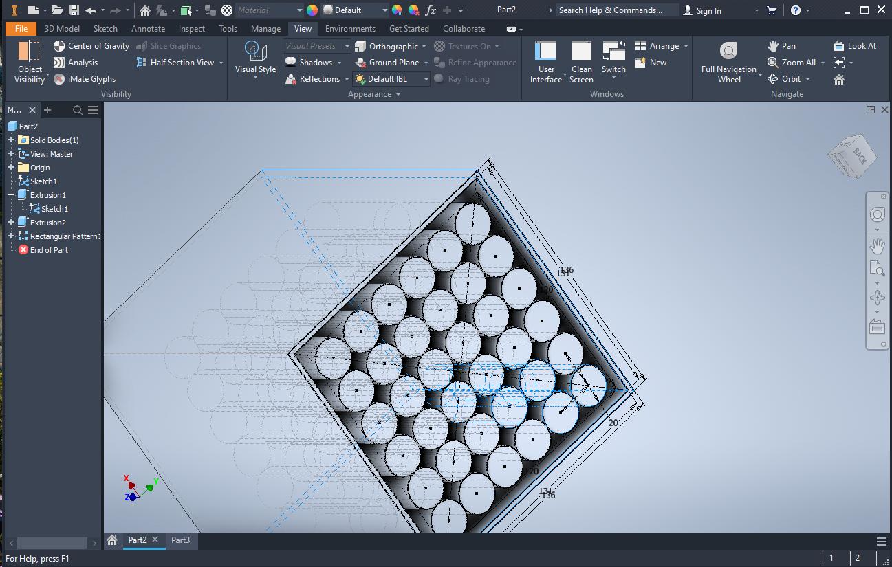
Here's my effort assuming that your 300mm x 240mm inside triangle area doesn't include the space in the larger triangle that's taken up by the pivot arm and spring suspension (10 1/16" length = 255.6mm and 5 9/16" = 141.3mm, then 10 7/8" = 276.3mm and 6 7/16" = 163.5mm). As you can see there is more space vertically between the cells in the diagram so i took that into account when figuring the actual minimum height dimension. The diagram i used was the actual 18mm cell size. There should be enough room for sufficient padding in the enclosure to absorb any bumps along the way. Keep us posted on your winter project. It took me two months doing alot of figuring and refiguring before beginning my first build and that was after i had most of the materials, kit, cells, etc. I've learned more times than i'd like to admit that haste makes waste. You may even want to buy a few more cells than you'll actually need for your finished pack.
Thank you, the images look pretty clean, did you use some kind of program for it? I've been fiddling around with the tool from the russian site but it's hard to get exact dimensions and straight lines i kinda moved on to using auto desk inventor
I'm not sure how much space each cell would take, i'm assuming it's 18mm without the wrap, I was thinking of putting a layer of kapton/fiber tape between cells (i've seen it used here and there) which also take up some space. in inventor i've been using 20mm as cell size to be safe.
Not something useful, just experimenting to get an idea
I've thought about just modeling an enclosure and see if some company can cnc it, i have no idea about costs or where though.
also don't have much experience doing something like this but been learning cad on and off for a while.
vanturion said:
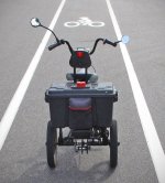
Here's how I did mine with a similar full-suspension frame and BBSHD kit which may help you in your planning:
I went with an EM3EV triangle pack 14S6P before they changed to hard-case (absolutely great capacity, I love it)
That looks like a nice bike!, did you have any issues with the crank arms being too narrow and nearly hitting the rear triangle?
i have yet to find some crank arms that can fit.