• Howdy! we're looking for donations to finish custom knowledgebase software for this forum. Please see our Funding drive thread

splitting my pack...need some guidance

zerogee

1 W
Joined
Mar 24, 2013
Messages
62
Location
Winnipeg, Manitoba, Canada
I have a Golden Motor 48V 10Ah pack that I need to do a 50/50 or a 60/40 split which ever is the best fit.

I have seen the Guide to Split Packs Appendix found in the Ping Battery Wiring Guide http://www.pingbattery.com/content/wiringguide.pdf and it looks similar to what I would like to accomplish.

Here's  a look at what's inside my pack... http://www.goldenmotor.ca/FAQ/questions.php?questionid=11


Please correct me if I'm wrong, in order to perform this split it looks like I would need to split the large black neg (-) discharge wire that goes from the key switch to the BMS, replace the appropriate copper bus bar with a wire, split the small red positive (+) charging wire that goes from the charging port to the BMS and split half of the smallest red BMS sense wires.


This pack has a key (power) switch, will this provide some protection against shorting when performing these operations? What  other precautions need to be taken? Is there an ideal order I should split /disconnect the wires? And connect the wires? Should I follow the order given in the guide?


Is it possible to make the connection between the 2 packs with a single multipin socket? Can you recommend some connectors?


Any other recommendations?


Thanks,

Myron  
 
To split the battery, you will need to lengthen the wires to the bms on those cells that will not be so close to the bms anymore.

Then a longer wire connecting the + of one section to the - of the other. And a longer wire from the + or - of the more remote section to the bms, as the case may be.

At all times while you work on this, you are liable to short. Nothing will protect you from sparking except care and common sense. NEVER have a + wire and a - wire with both stripped and exposed at the same time.

Take lots of care with tools, so you don't connect + and - with a metal tool as you go.

Pesonally, I don't undersand why you want to split such a small battery in half. A huge 48v 20 ah makes more sense, but that looks to me like it weighs under 15 pounds.
 
The pack is for my mountainboard.
http://youtu.be/uyMaEkHo7hQ

Right now the battery placement makes the board /wheel top heavy. I'm thinking if I could split the pack and mount half under the deck inside of the frame and the other half on the deck between the feet it will improve the balance.

Sounds like I'm on the right track though. Does it matter what order things are done? Is there a single multipin connector that can be used to make the connection between the packs or should I use seperate connectors?
 
You will absolutely have to keep those wires in the same order or you will damage or destroy the BMS through a short. If you must do this, do one wire at a time, cut it in the middle and lengthen it. Keep the same connectors in the same order on the end(s). I have done this successfully on 2 Ping batteries but both were 20 A/hrs, and I needed to balance the trike. I sure would not do it if I did not have to.
otherDoc
 
do not use connectors inside a battery pack. use large diameter wire to connect the two sections together and for the sense wire on top of the lower pack, attach that sense wire in the middle of the wire connecting the two sections.
 
docnjoj said:
You will absolutely have to keep those wires in the same order or you will damage or destroy the BMS through a short. If you must do this, do one wire at a time, cut it in the middle and lengthen it. Keep the same connectors in the same order on the end(s). I have done this successfully on 2 Ping batteries but both were 20 A/hrs, and I needed to balance the trike. I sure would not do it if I did not have to.
otherDoc

I was planning on working on one wire at a time. Easiest way of keeping track of things and reduce the risk of shorting something for sure.

What I was wondering if it mattered if I started on the small red BMS sense wires, or the large black negative discharge wire, or replace the pack bus bar with wire. Then which should be worked on second. Then which should be done next. The small red charging wire could probably go last.
 
dnmun said:
do not use connectors inside a battery pack. use large diameter wire to connect the two sections together and for the sense wire on top of the lower pack, attach that sense wire in the middle of the wire connecting the two sections.

That's a bummer. I was hoping I could make the pack easier to install on and remove from the board with the cable(s) going through the deck. A cleaner install too.
 
because of contact resistance, it will cause the BMS to cut out for LVC on the cell adjacent the wire to the other part of the pack. so it has to be soldered and large diameter cable, 12AWG up to 40A and 10AWG over that imo.

you have to put the sense wire in the middle to split the delta voltage between the two adjacent cells on each side of the connection.
 
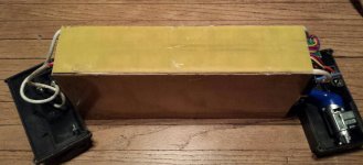
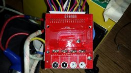
Finally getting around to spitting the pack. It is very different than the GM pack in the link in my OP. This looks well put together and fits inside the aluminum housing like a glove. Not shrink wrapped instead covered on all sides with a sheet of G10 held on with double sided tape. Cells are covered in a foil. The cells are spot welded together with metal bus strips and taped together with packing tape. No threaded stud terminals. The main wires are sleeved. The sense wires are neatly organized and seperated. Very small enclosed BMS. Here's a look inside...

PicsArt_03-22-11.45.20_resized_3.jpg

PicsArt_03-22-11.46.07_resized_3.jpg

View attachment 4


PicsArt_03-22-11.47.57_resized_3.jpg

PicsArt_03-22-11.48.41_resized_3.jpg

View attachment 1

PicsArt_03-23-12.04.17_resized_1.jpg
 
All that is needed to split the pack is cut the packing tape between the 2 cells, remove that sense wire and cut that bus strip. Because I can optimise the orientation of the 2 packs (it will be a 60/40 split) it appears I will only have to solder the appropriate length of bus wire to rejoint the 2 packs. Solder that sense wire to the middle of that bus wire. No other wires will need to be split. I may have to add length to the positive charge lead if I want to locate that next to the power. All in all not as bad as it first looked.
 
I wasn't sure if I could open the BMS or if things would fall apart on the inside with some of those screws.

20160405_115255_resized_1.jpg
I can't see the other side. The heatsink is bonded to the FETs.
 
Back
Top