Example:
Yea - I was bound by NDA, and before that bound by threat of death - (I took part in the original Validation while working with a clearance ... at a place so serious that we were not even allowed to LOOK at the internet without risking an infraction) - but the information is freely accessible to all on the internet now so -
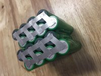
Its super easy to visualize how the internal monitors pick up the signal from "the common bus" where any individual cell fuse falling out can not cause a failure mode (undetectable situation where current can go thru a cell without monitoring its state)
So - my language above is incorrect - but the philosophy is correct.
Module, block, whatever - at the lowest level - we go Parallel then Series ALWAYS
NEVER Series and then parallel
...
The only time I have ever gone Series then Parallel was to leverage COTS design. Sadly the COTS design we leverage around here is targeted at the RC industry - so ... usually maxing out at 6S or 8S (traditionally). This drove a Series then Parallel build pattern for easy of use. Flawed... but for personal use... and never a production intent.
...
And to qualify another statement...
If one builds Parallel then Series you do not even need the heat shrink housings on the cans. They can just stack up against each other, so long as the transitions to Series are isolated.
...
SO
With my lego connectors (which sit on the bench in front of me but I am too lazy to take a pic)...
I have packed in 4 different 18650's
Yellow, Blue, Green, Brown
Yellow is the tightest fit
Brown is the loosest fit
Presumably differences (thousandths of an inch) in the insulator selection and not in the actual can dimension
...
Getting back to this thread...
We dont really need a #0000 buss bar in there.... Just look at the bars used in something like a Tesla Pack that can dump 1000A!!!
We are running more like 30A or 40A constant
Maybe at absolute most bursts to 80A
Good design dictates the following:
Assume a 1kwh pack (because that is a big ass ebike pack)
Assume 14S - as that is "about 50V"
1KWH/50V = 20AH
So - for a 1kw pack in 50V we will need 20Ah of cells
Conservatively assume 2Ah per cell (after degradation)
Thats a clean 10P
So a 10P14S pack (not a 14S10P!)
In this case we will see the following:
Average current of 40A continuous
Spread across 10 cells
4A per cell (Quite reasonable)
Assume 100% margin on fusing current
Peak currents of 8A during WOT for short periods
So... 16A fusing
A 26AWG exposed wire will fuse after 10 seconds
Adding margin
Reviewing amapcity charts
Even the most conservative ampacity chart
For enclosed wire
With 100% margin, on top of 100% margin (to avoid heating cells)
24AWG per cell would be considered hugely conservative
... in this case ...
The bus
... 40A continuous, 80A burst, enclosed
10AWG to 6AWG is a ballpark range
...
From my own testing in representative systems with a 40Aish current limit
10AWG does not get warm
12AWG does get warm
So adding a bit of margin - 8AWG would suffice for any of this business
The cross sectional area of "1/2 inch copper pipe"
5/8" OD (0.625)
Variable ID .528 to .569
Grabbing a conservative nominal of ID = .545 we get
0.625 - 0.545 = .080 thickness
Divide that by 2 to get a single wall, so 40 thousandths
Use calculus to calculate cross-sectional area:
https://www.engineeringcalculator.net/cross_section_properties.html
t = 0.040
r = 0.3125
A=2⋅π⋅r⋅t = 0.07854 in2
To check that for sanity...
50.6708664mm square
Going back to the charts we see this equates to between 1AWG and #0
(errr... sounds too big)
Using an independent measure for order of magnitude sanity (weight)
.344lbs per foot for 1/2" copper pipe
1AWG is about 258lbs/1kf, so .285lbs per foot
#0 is about 326lbs/kf, so .326
Confirmation thru two party verification that a half inch copper pipe is equivalent to something between 1AWG and #0
... moving on...
Ampacity on a 1AWG (to round down) is as follows:
super conservative... something like 130 to 150A
Since current is a squared problem... we roll back...
8AWG can carry 40A continuous - so - say 3 of those in parallel...
Meh - carry the two...
Looks like we have a margin of 2X to 3X
SO
Copper pipe is a bit of overkill
...
Going back to my suggestion of using a solder pot, I have the following real life personal experience
1) Grab some cheap ground wire from HomeDepot in 6AWG
2) Pull it straight and then run it thru the solder pot - coat the whole bastard
3) How you get your "solder dots" onto your cells is your business... top is easy... bottom is sketch
4) I am going to use 26AWG for my little fuse wires - they will tin easy - and I will tin them in the same way - as a roll
(so tin first then cut... as tinning the ends of a thousand short cuts will... lol... not work out)
5) Now assuming we have solder dots on the cells and a tinned buss bar... using tweezers... I will lay in my fuse connections
Thats my plan
The best way I can think of to "tin" an 18650 is to "tack" on tabs then tin those tabs (where we are just learning here...)
Tack welder goes real fast, is easy to make at home now, and the nickle tabs will be fine for tinning a little dot to
... Where the tabs rip off easily later
Where we dont have to solder directly to (sink heat into) our cell bottoms
Maybe... er... we go ahead and tack directly to the top... but we tab the bottoms...
...
Where we converge on the idea that we could then just tack longer tabs and solder those directly
")
... Anyway ...
I guess part of my point is all the fuss around load sharing and super heavy interconnects is pure bullshit. Dynamically it wont matter. Statically all of it will come into equilibrium. We are not running enough current or power to care and the bursts we are running are only 2X...
So... Dont sweat silly little details like exactly how long the little fuse wires are... or tapping "both ends" of the 6AWG (or in this case 1AWG) buss... it all works out and matters not. Ohms Law settles that... and the only time it is untrue would be in a short-circuit dump test.
Remember fusing
-methods


 View attachment 2