
You are using an out of date browser. It may not display this or other websites correctly.
You should upgrade or use an alternative browser.
You should upgrade or use an alternative browser.
Sur-Ron - New Mid drive Bike
- Thread starter Allex
- Start date
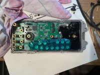
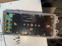
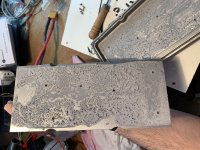
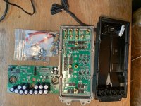
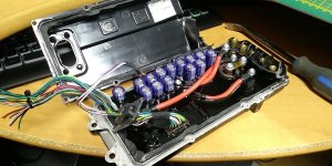
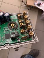
Hi, so i finaly clean off potting. It took me about 5 hours, I have cooked it in owen for 100C, and then heat with hot air gun and repeated this about 3times. And with some wood stick peel of potting. I have damaged some caps and some resistor - nothing big... Only connector connecting power stage and control board is damaged - i will replace it. So boards i hope will work.
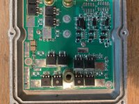
Control board :
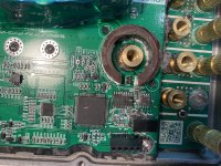
CPU : Nuvoton NM1530VE3AE (ARM Cortex-M0, 50 MHz, 128 kB ROM, 16 kB RAM)
Halls are THT with iron core? Allegro A1308 (UA pinout)
Hall amplifier MCP6021 - hope i can only change feedback for moooore amps.
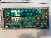
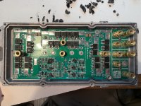
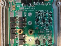
Power board: nothing suprising here")
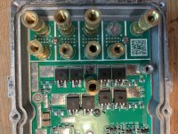
Fets:IPB042N10N3 (100V,4.2mOhm,137A) - 4 paralel, PCB is for 6 paralel so i will buy some and add them for more amps, but they are currently soldout everywhere :/
Gate drivers are :IR2127S - output boosted with transistors
there are RC snubbers network everywhere on gate signals, between VBAT and phase, phase and gnd. Gate resistors are 20R.
I did not find any battery shunt... I can closely look on traces if they are measuring voltage drop on PCB but i thing they calculating it from two phase current sensors - that is what i expect because when i start measuring batt amps it was 60A and after some riding it rises to 62A - halls is drifting, so battery current will also drift.
Filtering electrolytes from control board are connected through spacers to power stage.
Control board :
CPU : Nuvoton NM1530VE3AE (ARM Cortex-M0, 50 MHz, 128 kB ROM, 16 kB RAM)
Halls are THT with iron core? Allegro A1308 (UA pinout)
Hall amplifier MCP6021 - hope i can only change feedback for moooore amps.
Power board: nothing suprising here
Fets:IPB042N10N3 (100V,4.2mOhm,137A) - 4 paralel, PCB is for 6 paralel so i will buy some and add them for more amps, but they are currently soldout everywhere :/
Gate drivers are :IR2127S - output boosted with transistors
there are RC snubbers network everywhere
on gate signals, between VBAT and phase, phase and gnd. Gate resistors are 20R.I did not find any battery shunt... I can closely look on traces if they are measuring voltage drop on PCB but i thing they calculating it from two phase current sensors - that is what i expect because when i start measuring batt amps it was 60A and after some riding it rises to 62A - halls is drifting, so battery current will also drift.
Filtering electrolytes from control board are connected through spacers to power stage.
Attachments
-
 IMG_1617.JPG456.9 KB · Views: 2,471
 -
 IMG_1621.JPG453.1 KB · Views: 2,471
 -
 IMG_1622.JPG552.7 KB · Views: 2,471
 -
 IMG_1623.JPG435.6 KB · Views: 2,471
 -
 IMG_1626.JPG434.9 KB · Views: 2,471
 -
 IMG_1627.JPG522.1 KB · Views: 2,471
 -
 IMG_1628.JPG530.6 KB · Views: 2,471
 -
 IMG_1630.JPG568.3 KB · Views: 2,471
 -
 IMG_1631.JPG598.5 KB · Views: 2,471
 -
 IMG_1632.JPG545.3 KB · Views: 2,471
 -
 IMG_1633.JPG339.1 KB · Views: 2,471
 -
 IMG_1634.JPG606.8 KB · Views: 2,471
Elektrosherpa
1 kW
- Joined
- Feb 7, 2021
- Messages
- 386
WOW... I never thought it would be possible to peel off that stuff... :thumb:
(well-it wouldnt help me at all, but interesting to see )
(well-it wouldnt help me at all, but interesting to see
)Very interesting. Thanks for posting.
Looks like they got cheap and didn't populate all the power stage FETs.
I've never been able to find a datasheet for those FETs either. No idea what their ratings are.
Your mezzanine connectors look not so good now. Those will need to be replaced.
Looks like they got cheap and didn't populate all the power stage FETs.
I've never been able to find a datasheet for those FETs either. No idea what their ratings are.
Your mezzanine connectors look not so good now. Those will need to be replaced.
noneedlessnoise
1 mW
- Joined
- Oct 19, 2018
- Messages
- 15
Has anyone adapted a Kelly or Sabvoton controller to the Sur Ron?
mxlemming
100 kW
- Joined
- Jul 17, 2020
- Messages
- 1,125
Infineon ipb042n10fechter said:Very interesting. Thanks for posting.
Looks like they got cheap and didn't populate all the power stage FETs.
I've never been able to find a datasheet for those FETs either. No idea what their ratings are.
Your mezzanine connectors look not so good now. Those will need to be replaced.
4.2mohm, 6300nF Cinput 100V
See the video below (sound on) for the slow throttle response of our ASI BAC4000 controller. Do you BAC4000/8000 folks know if it's the controller's behavior or that it can be configured to respond better?
Also I'm looking for a tuned ASI parameter list for the Surron motor. We have access using the BacDoor mobile app (bluetooth). Maybe someone is willing to provide one? The BAC4000 is running on v6.015 firmware, using a 60V battery. A parameter list for 72V would be fine too. Thanks a lot!
https://www.youtube.com/watch?v=kN6_h_5qU80
liveforphysics
100 TW
Looks like nice hotrodding potential. FET swap for some ~2mOhm parts, and populate fully to 6 per parallel group, and in an identical size and weight package you're running more than 2x continuous power (assuming PCB traces and caps handle it) for the same heat load, with a burst current potential increase around ~3x (for same Si dice heating rate during burst).
Respect to your determination to dig all the potting out, I dug at it for 10 minutes and decided I didn't want it badly enough, but I'm grateful for your hard work.
As this topology is only a trace footprint reconfigure away from running any of the sits on top PCB packages, it would be exciting to see them reconfigure for these little guys.
Ti MOSFET CSD19536KTT
Space available to package a few more of them on the board, get 8 per parallel group of that Ti FET, beef up critical traces with some added copper bus bars (and replace brass current carrier studs with copper), and the controller would be ready for >35-40hp bursts (not saying the battery and motor are ready for that).
Very useful tear down, great work! Looking forward to your results after modding it.stepus said:Hi, so i finaly clean off potting. It took me about 5 hours, I have cooked it in owen for 100C, and then heat with hot air gun and repeated this about 3times. And with some wood stick peel of potting. I have damaged some caps and some resistor - nothing big... Only connector connecting power stage and control board is damaged - i will replace it. So boards i hope will work.
I wonder if it would be possible to read/dump the firmware, the Nuvoton MCUs are documented well. They may have enabled a security lock, otherwise reading the firmware should be possible. After that you could even mod a lot further :wink:
Hi, i have repaired everything i broke when i deppoted it, and i tested it and it still rides !  i thing i have a more lucky then sense :lol: i have ordered same fets and they will arrive at next week...
I was already thinking about dumping FW - but I don't think it will go easily to modify hex file...
unfortunately you are right, this controller will be a hotrodder i cannot change ratio of battery amps / phase amps.
I can shunt only phase amps. Now controller drawing aprox 62Amps battery and 350A phase amps. So if i wanted to 10kW of power its aprox 160Amps battery, and with unchanged ratio battery/phase amps i will get 900 phase amps - quite huge current - probbably i will not go that high...
I was already thinking about dumping FW - but I don't think it will go easily to modify hex file...
unfortunately you are right, this controller will be a hotrodder
i cannot change ratio of battery amps / phase amps.I can shunt only phase amps. Now controller drawing aprox 62Amps battery and 350A phase amps. So if i wanted to 10kW of power its aprox 160Amps battery, and with unchanged ratio battery/phase amps i will get 900 phase amps - quite huge current - probbably i will not go that high...
If you succeed dumping please sharestepus said:I was already thinking about dumping FW - but I don't think it will go easily to modify hex file...
no, i didnt tried yet. I was looking for programmer and it needs something called NuLink i have only ST-link,USB asp etc... I'll try to find someone I can borrow it from. I don't want to buy a programmer so that I can find out that it can't be dumped I have no experience editing hex, so someone from the community from here could look.
i have only ST-link,USB asp etc... I'll try to find someone I can borrow it from. I don't want to buy a programmer so that I can find out that it can't be dumped I have no experience editing hex, so someone from the community from here could look.stepus said:So if i wanted to 10kW of power its aprox 160Amps battery, and with unchanged ratio battery/phase amps i will get 900 phase amps - quite huge current - probbably i will not go that high...
It works fine at 180 battery amps. You won't actually get 900 phase amps.
Doctorbass
100 GW
liveforphysics said:As this topology is only a trace footprint reconfigure away from running any of the sits on top PCB packages, it would be exciting to see them reconfigure for these little guys.
Ti MOSFET CSD19536KTT
Space available to package a few more of them on the board, get 8 per parallel group of that Ti FET, beef up critical traces with some added copper bus bars (and replace brass current carrier studs with copper), and the controller would be ready for >35-40hp bursts (not saying the battery and motor are ready for that).
I got one of these controller sur ron X, apparently deffective, maybe a mosfet set blown. I am interested to try that upgrade Luke.. It seem a stock 24 fet made for 36fet too.
Probably the cheapest way for them was the 4 parallel fet per side per phase with the price of 24fet lower rds on being cheaper than 36 fets with higher rds on...
the CSD19536KTT seem as expensive as the IRF4110 were back in 2008, at 5.20usd each..
Doc
liveforphysics
100 TW
$/Amp price on them is much better than the old 4110's though.
Hummina Shadeeba
1 MW
maybe there's a temp you could heat the esc in an oven and not damage the bits on the pcb so the potting material would get soft and be more easily removed. or maybe thats how you did it
Doctorbass
100 GW
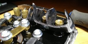
Hey guys I have to say it take ton of patience to just remove the plastic cover! I pried 2 screwdriver and i tought multiple times i had forgot some screw hidden somewhere but not!! the plastic cover is glued also to the internal poting. This make all surrounding edge very strong to unstick from the aluminum plate. Stepus and other that dissassembled it you deserve respect!! :thumb:
I myself dissassemble ton of stuff including the famous DYSON battery where the cells have glue between the cell holder and cells inside the tube!... but that damn controller was way harder than a Sevcon size 6!!
Even by taking maximum care i also ended out damaging one of the rail capacitor.
The Sur Ron X controller i got have a phase B shorted to NEG and POS. It is as clear as earth is not flat that this controller has been made to Not be servisable!!!
But seriously removing all the puty dremel, oven, all kind of mecanical or thermodynamic method is not so easy! I realy have to find that famous magic sauce to dissolve putty.. but i hate toxic stiff like that!
I myself dissassemble ton of stuff including the famous DYSON battery where the cells have glue between the cell holder and cells inside the tube!... but that damn controller was way harder than a Sevcon size 6!!
Even by taking maximum care i also ended out damaging one of the rail capacitor.
The Sur Ron X controller i got have a phase B shorted to NEG and POS. It is as clear as earth is not flat that this controller has been made to Not be servisable!!!
But seriously removing all the puty
Doctorbass
100 GW
liveforphysics said:$/Amp price on them is much better than the old 4110's though.
The powerfull Fet have so much improoved since 10 years! Luke! The great old time where 4110 were the king of the place to tripple power of simple cheap crystalyte controllers and where adding some solder to the shunt was the 2nd method to get more power lol
Doc
Doctorbass
100 GW
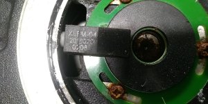
The current sensor seems very interesting.
It is a "C" shape iron core with a hall sensor between the two ends.
Notice that on the version i got the poting continue all the way up to the phases and power input leads and suround them with the plastic cover lower parté I had to tear it apart to be able to remove the cover.
I'm sure that the ingres portection is nice on these one and even the ingres of screw driver inside is also well prevented :lol:
Doc
Attachments
Doctorbass
100 GW
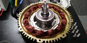
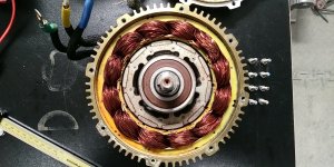
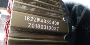
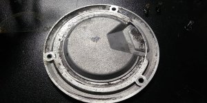
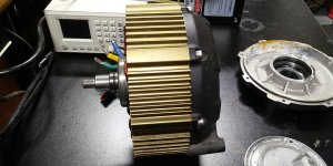
Not sure there was pictures of the Sur Ron motor so i opened one ( a 2018) for your own pleasure :wink:
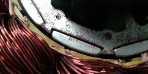
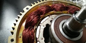
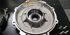
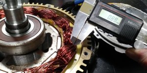
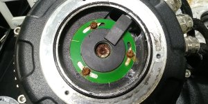
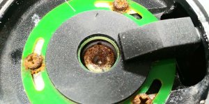
that motor had Hall sensor problem making the bike to have some cut out. We can see that there was water intrusion inside on the hall sensor cover and that it went down to the stator core base. The humidity made light rust everywhere inside.
I did not found any drain hole or chanel on that motor.
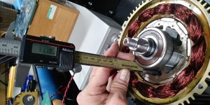
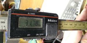
Lamination seem to be 0.35mm visually i was not able to measure it.
The winding is made of 0.88mm strands ( gauge 20 + insualtion thickness) and each phase see to have enough to make a 6 or 8 gauge equivalent.
The phase to phase inductance is about 50uH.
DC resistance phase to phase ( manually measured with 4 wire kelvin method using Fluke 189 milivoltmeter and Xantrex XFR 100-12 current source:
Yellow to Green: 10.158miliohms
Yellow to Blue: 9.907miliohms
Blue to Green: 10.098miliohms


The rotor width is 32mm
there is plenty of room left inside both side covers
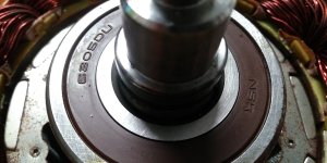
Bearing are NSK 6305DU and there is a rubber seal inside the bearing hole of the side covers
Doc
that motor had Hall sensor problem making the bike to have some cut out. We can see that there was water intrusion inside on the hall sensor cover and that it went down to the stator core base. The humidity made light rust everywhere inside.
I did not found any drain hole or chanel on that motor.
Lamination seem to be 0.35mm visually i was not able to measure it.
The winding is made of 0.88mm strands ( gauge 20 + insualtion thickness) and each phase see to have enough to make a 6 or 8 gauge equivalent.
The phase to phase inductance is about 50uH.
DC resistance phase to phase ( manually measured with 4 wire kelvin method using Fluke 189 milivoltmeter and Xantrex XFR 100-12 current source:
Yellow to Green: 10.158miliohms
Yellow to Blue: 9.907miliohms
Blue to Green: 10.098miliohms
The rotor width is 32mm
there is plenty of room left inside both side covers
Bearing are NSK 6305DU and there is a rubber seal inside the bearing hole of the side covers
Doc
Attachments
-
 20210506_000053.jpg340.4 KB · Views: 1,866
 -
 20210506_000117.jpg367.5 KB · Views: 1,866
 -
 20210506_000130.jpg217.1 KB · Views: 1,866
 -
 20210506_000201.jpg296.1 KB · Views: 1,866
 -
 20210506_000220_HDR.jpg375.8 KB · Views: 1,866
 -
 20210506_000235.jpg185.3 KB · Views: 1,866
 -
 20210506_000318.jpg266.3 KB · Views: 1,866
 -
 20210506_000342.jpg214.3 KB · Views: 1,866
 -
 20210506_000448.jpg327.1 KB · Views: 1,866
 -
 20210506_000616.jpg336.1 KB · Views: 1,866
 -
 20210506_000629.jpg418.8 KB · Views: 1,866
 -
 20210506_000800.jpg267.2 KB · Views: 1,866
 -
 20210506_000704.jpg290.3 KB · Views: 1,866
 -
 20210506_000938_HDR.jpg314.3 KB · Views: 1,866
 -
 20210506_000945.jpg192.7 KB · Views: 1,866
 -
 20210506_001041.jpg319.3 KB · Views: 1,866
 -
 20210506_001103.jpg173.1 KB · Views: 1,866
motomoto
1 kW
- Joined
- Jun 28, 2010
- Messages
- 458
Seems crazy to me watching Luke and Doctorbass playing with stock Sur-ron controllers and motors, when they have done
the most bad ass stuff on the planet, far beyond the power of this bike. Hasn't Luke taken this bike way beyond what is even possible 2 years ago?
the most bad ass stuff on the planet, far beyond the power of this bike. Hasn't Luke taken this bike way beyond what is even possible 2 years ago?
Hi, can you measure motor winding resistance ?
About deppoting, it's quite difficult, I recommend unscrewing the screws from the plastic cover and put the controler to the owen, but iam not sure if plastic cover and wires will survive. Plastic cover has a groove that is glued with silicone, and then they pour potting compound inside controller, and potting also rises in chimney at terminals. I had a luck i broke only (-) Battery terminal and did not damage much plastic cover... After i took off plastic cover i slightly heated up aroud connector, and started deppoting, and carefully disconnecting connector. After i took off wires with plastic cover i wrapped the capacitors and the connector with Kapton tape and baked it in owen at about 100celsius. I deppoted it with a toothpick, and other woodstick, i was able to slipped between potting and board without damage. I baked it about 3 times, and when i was deppoting i helping it with hot air gun also.
About future tunning :
I have ordered 20 fets from RS-online - they have on stock 60pcs, but when i ordered them they found out that only have 10 pieces in stock. So i will have only 10pcs of IPB042N10N3, but i find they do same chip with same package, but legs are straight, not bended for SMD soldering, its called IPI045N10N3, but everthing looks same, they have same datasheet but only different thing looks RdsOn, and current ratings are worse. So i ordered another 2 pcs of them, and i will bend legs manualy.
https://www.tme.eu/Document/f0cfc0a355bb37fce6ed90a4c3500c4b/IPI045N10N3G-DTE.pdf
my question is, after i will have fets, what do you prefer ? put this weaker fets in upper transistor array or a lower ? High side transistors are more loaded at duty over 50%, and lower fets with duty 0-50%. So it will be better to put them on High side so low side will be stronger for phase amps ? I will place them on two phases, so two phases will be a little weaker at high side?
thanks for advise
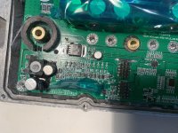
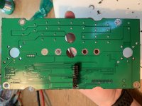
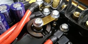
I also did some current carrying and mechanical strengthening on terminals, because they break from board very easily without potting
About deppoting, it's quite difficult, I recommend unscrewing the screws from the plastic cover and put the controler to the owen, but iam not sure if plastic cover and wires will survive. Plastic cover has a groove that is glued with silicone, and then they pour potting compound inside controller, and potting also rises in chimney at terminals. I had a luck i broke only (-) Battery terminal and did not damage much plastic cover... After i took off plastic cover i slightly heated up aroud connector, and started deppoting, and carefully disconnecting connector. After i took off wires with plastic cover i wrapped the capacitors and the connector with Kapton tape and baked it in owen at about 100celsius. I deppoted it with a toothpick, and other woodstick, i was able to slipped between potting and board without damage. I baked it about 3 times, and when i was deppoting i helping it with hot air gun also.
About future tunning :
I have ordered 20 fets from RS-online - they have on stock 60pcs, but when i ordered them they found out that only have 10 pieces in stock. So i will have only 10pcs of IPB042N10N3, but i find they do same chip with same package, but legs are straight, not bended for SMD soldering, its called IPI045N10N3, but everthing looks same, they have same datasheet but only different thing looks RdsOn, and current ratings are worse. So i ordered another 2 pcs of them, and i will bend legs manualy.
https://www.tme.eu/Document/f0cfc0a355bb37fce6ed90a4c3500c4b/IPI045N10N3G-DTE.pdf
my question is, after i will have fets, what do you prefer ? put this weaker fets in upper transistor array or a lower ? High side transistors are more loaded at duty over 50%, and lower fets with duty 0-50%. So it will be better to put them on High side so low side will be stronger for phase amps ? I will place them on two phases, so two phases will be a little weaker at high side?
thanks for advise
I also did some current carrying and mechanical strengthening on terminals, because they break from board very easily without potting
Attachments
I think you really want all the FETs to be the same and from the same batch so they are well matched.
I like the reinforcement on the terminals. I've seen a couple controllers fail when one of those cracked at the base. It won't hurt to put some epoxy around them when you get everything done.
I like the reinforcement on the terminals. I've seen a couple controllers fail when one of those cracked at the base. It won't hurt to put some epoxy around them when you get everything done.
I think that slightly different FETs will not affect so much. There are actual datasheets of them:
https://www.infineon.com/dgdl/Infineon-IPI045N10N3%20G-DS-v02_10-EN.pdf?fileId=5546d4625d5945ed015d9897792104f5
https://www.infineon.com/dgdl/Infineon-IPB042N10N3%20G-DS-v02_09-EN.pdf?fileId=db3a30431ce5fb52011d1e8b0cc31586
diference between these two is only 0.3mOhm (IPB 4.2mOhm, IPI 4.5mOhm)
Who knows if this difference is not only given by the package, because the IPI package has a drain on the foot and tab, and IPB has a on a tab.
But i will solder tab on IPI package - so it will be maybe same. Because when I look at the datasheets they are both the same only the RdsON is different. So it looks there is inside same chip, but RDSon is differently measured between TAB-Drain against LEG-Source on IPB package, and LEG-Drain against LEG-Source on IPI package.
BTW fets is good for paralering they will heat up individualy - higher RDSon on these fets, and more current flows through colder fets or with lower RdsON, - they will heatup too, and all transistors will equalize and have same current flowing.
Doctorbass
100 GW
stepus said:Hi, can you measure motor winding resistance ?
Yes it's done now, go back to my post :wink:
Doc
Similar threads
- Replies
- 3
- Views
- 1,052
- Replies
- 15
- Views
- 5,756
- Replies
- 2
- Views
- 734
- Replies
- 27
- Views
- 4,317