
Eastwood
100 kW
- Joined
- Jan 13, 2021
- Messages
- 1,479
You have moved weight around in the chassis that it wasn't intended for so things change
Yeah for sure
 Although the way I have the battery configured, it’s somewhat a “similar” shape to the actual stock engine. I took this in consideration what you’re saying about the weight being moved around in the chassis and that’s how I end up with this battery shape.
On a sidenote, I actually revalved the bike this morning Lol., I couldn’t help myself
 it’s not much work. It only takes about 45 minutes to remove the cartridges and tweak the shims and reinstall.
But it definitely needed to be done as yesterday I did some more extensive testing and it’s still harsh over sharp squared objects, even with the compression clicker turn all the way out.
So after the re-valve this morning, it’s much more plush and less harsh over squared Sharp objects.
Tweaked the low speed and high speed, Nothing too dramatic. I’m sure I’ll end up doing more re-valving once I have the final bike weight.
Next, I need to order the new main springs as I’m only using about 70% of the stroke. The race sag as of now for the forks is only 20 mm which is way way too stiff
According to race tech the Rmz 250 vs 450 the front spring rate is almost identical for my body weight so I’m thinking after I add the extra 10 to 15 pounds with the new battery, It shouldn’t be too much of a dramatic difference since race Tech has the 250 and 450 at almost similar spring rates for my specs.
RMZ 250cc .40kg/mm
RMZ 450cc .41kg/mm
My stock springs are .47kg/mm


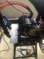


 Going to be a solid pack.I would definitely turn the controller over though why there is still time.One forces air in the heatsink and two keep the crap off all the wiring loom.The placement is 100% the best place for weight distribution so great job.


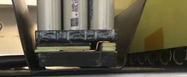
 so it’ll be in similar size as yours


