
You are using an out of date browser. It may not display this or other websites correctly.
You should upgrade or use an alternative browser.
You should upgrade or use an alternative browser.
Testing the big 15 and 20Ah LiFePO4 cells is tough! *Pics*
- Thread starter liveforphysics
- Start date
Dingo2024
100 W
details for 16 cells
15Ah cells
cell weight = 16 * 0.401g = 6.4kg, so less than 7kgs assembled as an estimate
stack of 16cells not including termination or BMS = 108.8mm * 150mm * 211mm
20Ah
16* 20Ah cells
cell weight = 16 * 0.467g = 7.5kg, so less than 8kgs assembled as an estimate
stack of 16cells not including termination or BMS = 110.4mm * 165mm * 227mm
hope this helps
Ian
stack of 16cells not including termination or BMS = 110.4mm * 165mm * 227mm
Thanks Ian,
which one of those dimensions is thickness?
Maybe I should think a moment before posting... 110.4mm must be the thickness, so one cell is about 6,9 mm thick, right?
Just wanted to compare with EIG 14 Ah cells I´m testing at the moment. It seems A123 15 Ah is about the same volume and 20 Ah is 9 % smaller per Ah.
Just wanted to compare with EIG 14 Ah cells I´m testing at the moment. It seems A123 15 Ah is about the same volume and 20 Ah is 9 % smaller per Ah.
Bobocop said:I don't mean (by what i'm saying) that the price is to high for the quality, What i mean is that it's to high for the average person to afford.
You must be one of those rich little kids that your parents work hard to support your habits.
Try working for it, and then you'll understand mypost.
Just because you're not talented enough with money and modern economic productivity doesn't mean everyone else who is was a "rich little kid".
John in CR
100 TW
booboocop,
$750/kwh is a great price for these cells. Sure I hope they come down significantly, but in the meantime the only things holding me back are that I already have about 8kwh of lithium cells with no plans to build an e-car yet, and I want to make sure all my ducks are in a row before I start working with $50/ea cells. Learning and blowing used toolpack cells at less the $2/ea is one thing, but messing up expensive cells that should last for a decade unless I mess them up is something all together different.
Cellman et al,
What's the big deal with cell terminations? Are the cells poorly matched or are failure rates high enough to need to take packs apart? Why not just solder/weld the tabs together and be done with it. Mechanical connections just seem like a waste of weight and money, and if anything put your pack more at risk due to connections that go bad down the road.
@John in CR
Bad cells are just a fact of life and if a simple easy and effective non solder/welding way of putting packs together is found then I think most people would want to go with that.
On the other hand you do have a point though.
I'd like to get a 12 cell 20AH pack going!
Bad cells are just a fact of life and if a simple easy and effective non solder/welding way of putting packs together is found then I think most people would want to go with that.
On the other hand you do have a point though.
I'd like to get a 12 cell 20AH pack going!
John in CR
100 TW
tropmonky said:@John in CR
Bad cells are just a fact of life and if a simple easy and effective non solder/welding way of putting packs together is found then I think most people would want to go with that.
On the other hand you do have a point though.
I'd like to get a 12 cell 20AH pack going!
How much QC testing do they go through before they're shipping out of the door? Can we do something to test them and identify the problem cells before putting our packs together? I just want a multi K cycle pack that I never have to fool with as long as I don't do something to mess it up. I'll run it conservatively from both a power and DOD standpoint. Getting 15 or 20ah with each set of tabs sure seems worth whatever little bit of trouble it might be to get a permanent connection. It's not like tab welding 18650 or 26650 cells any more, thank goodness, and this price is less than I paid for my lowly Ping packs 2 years ago.
cell_man
100 kW
Fellas, whether I was right or wrong I pushed on with the mechanical termination method. For high current cells like these I think a mechanical method does have it advantages and it's also DIY. Here's a pack I made up today
View attachment CIMG0645.JPG
View attachment 1
View attachment CIMG0647.JPG
The terminations add 220g to this 12S pack so less than 20g per cell. Adds about 7mm to the total length of the cells. Not a bit of wasted space I reckon. With BMS terminations etc, total weight about 5.2kg for a 12S 15Ah pack. Those 15Ah cells generally give 16Ah plus too.
docnjoj
1 GW
That is one classy pack, Cell_man!
otherDoc
otherDoc
cell_man
100 kW
Thanks, I'm just starting to get the hang of this I'm gonna update the for sale section and give the option to buy the termination parts or fully assembled packs. There's still a bit of work involved in making the parts and assembling a pack but it isn't so bad. I just soldered the positive and negative leads onto the rear of the the brass clamps, but might come up with a neater solution when I have a minute. I think the connections available as they are, makes the pack very flexible and easy to modify or add BMS sense wires. There's enough room to run more substantial wires to use a proper balance charger, 3.65V PSU on each cell. I definitely want to get that solution available and offer a simpler BMS, which just uses a signal to alert for LVC rather than FETs in line. High current BMS just gets too big. The BMS unit above is 30A constant but I'm running 2*25A controllers and it hasn't missed a beat.
Many people are overlooking the 15Ah cells but honestly they are a great cell and at moderate (if you call 100A moderate ) they have very similar voltage sag to the 20s. It's only when the current levels get really crazy that they start to lag behind the 20Ah cells.
I'm gonna update the for sale section and give the option to buy the termination parts or fully assembled packs. There's still a bit of work involved in making the parts and assembling a pack but it isn't so bad. I just soldered the positive and negative leads onto the rear of the the brass clamps, but might come up with a neater solution when I have a minute. I think the connections available as they are, makes the pack very flexible and easy to modify or add BMS sense wires. There's enough room to run more substantial wires to use a proper balance charger, 3.65V PSU on each cell. I definitely want to get that solution available and offer a simpler BMS, which just uses a signal to alert for LVC rather than FETs in line. High current BMS just gets too big. The BMS unit above is 30A constant but I'm running 2*25A controllers and it hasn't missed a beat. Many people are overlooking the 15Ah cells but honestly they are a great cell and at moderate (if you call 100A moderate
) they have very similar voltage sag to the 20s. It's only when the current levels get really crazy that they start to lag behind the 20Ah cells.Very nice and clean assembly!
Is there some reason that the BMS is on the "backside" from the cell termination?
How about an insulating sheet on top of the terminations, then BMS there with just long enough wires to let it flip to the side for access?
This would give
1. shorter both balancing and power wires
2. When put in a box, only need to open one side to access all the electrical connections (trouble shoot etc)
3. Likewise there is only one "fragile" side where an intruding object could cause a spectacular electric fire from shorting (after e.g. a fall or collision on the bike)
Your pack looks like it would fit excellent in the triangle of the Jekyll I just got to build up to an eBike.
I could keep the termination side protected by some sturdy metal attached to the rear/seatpost tube.
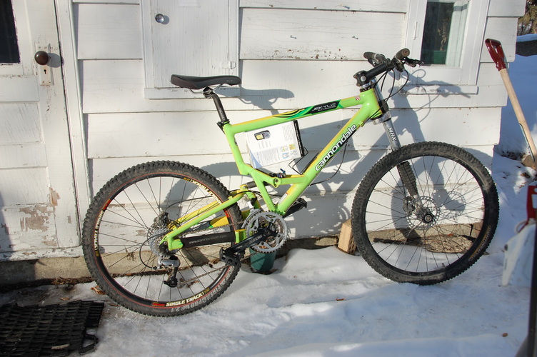
The box in the middle is exactly the dimensions of your pack (given the 15Ah cell dimensions you posted earlier).
Build of bike will likely be with BMC 1000W, but more on that in another thread.
Is there some reason that the BMS is on the "backside" from the cell termination?
How about an insulating sheet on top of the terminations, then BMS there with just long enough wires to let it flip to the side for access?
This would give
1. shorter both balancing and power wires
2. When put in a box, only need to open one side to access all the electrical connections (trouble shoot etc)
3. Likewise there is only one "fragile" side where an intruding object could cause a spectacular electric fire from shorting (after e.g. a fall or collision on the bike)
Your pack looks like it would fit excellent in the triangle of the Jekyll I just got to build up to an eBike.
I could keep the termination side protected by some sturdy metal attached to the rear/seatpost tube.
The box in the middle is exactly the dimensions of your pack (given the 15Ah cell dimensions you posted earlier).
Build of bike will likely be with BMC 1000W, but more on that in another thread.
cell_man
100 kW
Hi Jag,
my main reasons for putting the BMS there was to use up the wasted space on that end of the cells and avoid having to box cover up the terminals so I couldn't easily check the cell voltages. The far end of the cells is just a flexible material, so I just thought I could push the BMS into that end and use up what would ordinarily just be wasted space. I made a pack previously with a bigger higher current BMS and mounted it on the terminal end of the pack, mounted onto an insulating sheet, see below:

The above 16s 20Ah pack was boxed in with insulating sheets on all sides for some mechanical protection and then just heat shrink over the whole assembly. The layout is not set in stone, I'm happy to go whichever way works best for the customer/user as long as it doesn't compromise anything or make a lot of extra work.
my main reasons for putting the BMS there was to use up the wasted space on that end of the cells and avoid having to box cover up the terminals so I couldn't easily check the cell voltages. The far end of the cells is just a flexible material, so I just thought I could push the BMS into that end and use up what would ordinarily just be wasted space. I made a pack previously with a bigger higher current BMS and mounted it on the terminal end of the pack, mounted onto an insulating sheet, see below:
The above 16s 20Ah pack was boxed in with insulating sheets on all sides for some mechanical protection and then just heat shrink over the whole assembly. The layout is not set in stone, I'm happy to go whichever way works best for the customer/user as long as it doesn't compromise anything or make a lot of extra work.
That pack looks similar in layout to what I had in mind making. I'm aiming for a compact 12 or 16s 15Ah. Wanted to build a tight fitting aluminium box around it using ribbed alu sheets as sides to put some pressure on the cells. Also need to build a similar 8s pack for wife's bike.
Didn't decide yet on BMS. Was hoping to eventually use the new Fechter/Goodrum, but might go with something premade else to get started.
I like your plan to offer a smorgasboard of parts for those of us that want to do a custom assembly.
Didn't decide yet on BMS. Was hoping to eventually use the new Fechter/Goodrum, but might go with something premade else to get started.
I like your plan to offer a smorgasboard of parts for those of us that want to do a custom assembly.
liveforphysics said:CroDriver said:RoughRider said:@Cro
YOU ARE CRAZY...
lets say 300V*2000Amp * 2 = 1200kW...CRAZY
Ahhmm, thanks...?
5 20 Ah cells and 6 15 Ah test cells will be on my desk in a few days so we'll have more data in a couple of weeks
Still waiting on the fancy scope to come, and I will have graphs of 450amp discharge on the 15Ah cells, and 600amp discharge on the 20Ah cells. They are very much capable of it, and in a drag vehicle like you're proposing, he wouldn't be a concern for them at all.
Luke, have you made any progress on this one?
Do you know how much current I could expect from a 20Ah cell at normal ambient temperature (say 25-30*C), without too much sag (say 2,2V)?
And what could be the absolute maximum with heating the cells to 45*C and sag to 2.0V?
Thanks
jonescg
100 MW
Hi everyone; huddle around, we need your brains!
Paul and I are trying to devise a means to package the 4s3p packs such that overheating doesn't occur. Now, as I will be running twin Agnis on my E-moto, there is the potential for some serious current draw on the batteries. Maybe 800 A peak, 400 A continuous. As Luke determined, they get hot when discharged at high rates. This is clearly going to affect their lifespan so we need to come up with a way to get heat from the packs out to a sink where the air rushing past will cool them off.
So I wonder, given 6 kWh isn't much to lump around in a race situation, are we worrying about an amount of heat which will never happen before the cells are dead flat anyway? Or is there a real need to cool the packs from the get-go?
And how would we build the packs? Out of aluminium with sizable fins?
Your ideas are much appreciated!
Cheers,
CHRIS
olaf-lampe
10 kW
I guestimate the Agnis are not running on high voltage, so the risk of a shoottrought from pouch to pouch is low.
You could put alu-foil between the pouches and build the sidewalls and/or the bottom of the housing from Alu sheet. Make sure the alufoil is big enough to crunch up on every side to make good contact with the walls.
We once built a Kokam pack with 'L'-shaped alu-sheets instead of alu-foil ( 0,5mm thick) to make contact with a watercooled bottom. But I guess this is overkill here.
The critical time for the lifespan will be after the race. You should think about active cooling with external fans. ( like in Formula 1 for the carbondisk brakes )
Others are actually warming up their cells before the run ( 1/4 milers )
-Olaf
TylerDurden
100 GW
I posted this image of corrugated alu earlier in the thread, but that stuff might be hard to get.
Polycarbonate (lexan) fluted panels would be a way to get cooling between the slabs; it is readily available and less expensive than ally.

Avoid fluted polypropylene (coroplast), it will melt. IIRC, someone mentioned 'honeycomb' panels, that would insulate (bad).
Polycarbonate (lexan) fluted panels would be a way to get cooling between the slabs; it is readily available and less expensive than ally.
Avoid fluted polypropylene (coroplast), it will melt. IIRC, someone mentioned 'honeycomb' panels, that would insulate (bad).
cell_man
100 kW
Hi Chris,
I've got a design engineer friend visiting China at the mo and we made some progress on the box today. I think we've got a workable solution using 2mm aluminium sheet for side panels and 0.3mm between each cell. Most of the first box is made up now and I've got it fairly clear how it's going to be finished off. After that it's just a case of making the parts and then I'll try to get through them ASAP. Hopefully get the first shipment with 2 or 3 packs on the way to you soon
After working through the build a bit today I feel much better about the whole assembly. Maybe I've been worrying a bit too much. It really helps to be able to talk it through with an experienced design engineer, trying to just sit here and work through all the little details has been so difficult. A bit of re assurance and some new ideas is like a breath of fresh air
TylerDurden said:I posted this image of corrugated alu earlier in the thread, but that stuff might be hard to get.
Polycarbonate (lexan) fluted panels would be a way to get cooling between the slabs; it is readily available and less expensive than ally.
Avoid fluted polypropylene (coroplast), it will melt. IIRC, someone mentioned 'honeycomb' panels, that would insulate (bad).
Polycarbonate would be a poor choice, it has nearly identical thermal conductivity to polypropylene. Aluminum would be a good choice but I'm not sure why you'd want to use corrugated material unless you were running a coolant through it. Paul's plan sounds like a good one. I plan to cool my batteries similarly with thin Al sheets between them (possibly just Al foil or flashing) and clamping that to a heat exchanger with coolant running through it. Probably overkill but I want long term reliability.
jonescg
100 MW
cell_man said:Hi Chris,
I've got a design engineer friend visiting China at the mo and we made some progress on the box today. I think we've got a workable solution using 2mm aluminium sheet for side panels and 0.3mm between each cell. Most of the first box is made up now and I've got it fairly clear how it's going to be finished off. After that it's just a case of making the parts and then I'll try to get through them ASAP. Hopefully get the first shipment with 2 or 3 packs on the way to you soon
After working through the build a bit today I feel much better about the whole assembly. Maybe I've been worrying a bit too much. It really helps to be able to talk it through with an experienced design engineer, trying to just sit here and work through all the little details has been so difficult. A bit of re assurance and some new ideas is like a breath of fresh air
Great news Paul! It always helps when you have someone who knows what they're on about. I agree that you really need to conduct the heat out of the middle of the pack, and corrugated sheet wouldn't be up to the task. I'd been thinking about the boxes on occasion, but work has had me preoccupied of late. In the meantime, do you have the final dimensions of each pack? I can probably get started on the battery trays next week.
MitchJi
10 MW
Hi,
Posted this in the termination thread by mistake.
Be careful of rubbing and vibration!:
http://endless-sphere.com/forums/viewtopic.php?f=14&t=17497&p=256874#p256590
Posted this in the termination thread by mistake.
Be careful of rubbing and vibration!:
http://endless-sphere.com/forums/viewtopic.php?f=14&t=17497&p=256874#p256590
snowranger said:I am pretty sure my Ping died from vibration and shock rather than heat. All bad cell groups were at the ends of the pack, and there were obvious signs of fluid leakage at the bottom of the pack.
Yeah, that's why I put foam liner at the bottom where the battery sits. (Or, if it's in a bag, I don't use anything because the bag material itself has "give" to reduce peak shocks and evenly distribute the forces.)
A layer of cork sheet at about 1/4 inch thick is a good dampening material - which I use in my pack.
Assuming you charge every 20 miles, that's only 250 cycles you had on your Ping. Significantly lower than the claimed 1000+.
snowranger said:I was using that interlocking foam they sell at Costco for playrooms and such. Tried to make it tight enough that the pack wouldn't move around. Even so, the constant jarrring somehow wore down the cells.
Lots of rubbing goes on inside the battery bag or box. Hopefully the shrink wrap used now will help with that vs the duct tape that was on the early packs.
That's why I make the super tight fitting inner boxes custom fit to my pings. There is just no movement at all, and all the rubbing goes on on the outside of the tight box. I have some areas on ping 1 that rubbed quite a bit of the aluminum box away, but remove the battery, and the duct tape still looks cherry.
On some nicad packs I have, it didn't take long to start putting some serious rub marks on the cell cans. I didn't protect them so good, and quickly realized I needed to do more, even with metal canned cells.
liveforphysics
100 TW
maxvdh said:TylerDurden said:I posted this image of corrugated alu earlier in the thread, but that stuff might be hard to get.
Polycarbonate (lexan) fluted panels would be a way to get cooling between the slabs; it is readily available and less expensive than ally.
Avoid fluted polypropylene (coroplast), it will melt. IIRC, someone mentioned 'honeycomb' panels, that would insulate (bad).
Polycarbonate would be a poor choice, it has nearly identical thermal conductivity to polypropylene. Aluminum would be a good choice but I'm not sure why you'd want to use corrugated material unless you were running a coolant through it. Paul's plan sounds like a good one. I plan to cool my batteries similarly with thin Al sheets between them (possibly just Al foil or flashing) and clamping that to a heat exchanger with coolant running through it. Probably overkill but I want long term reliability.
If you check out my thermal images, even under the worst of situations, just the heat-spreading effects of a thin sheet of aluminum or copper roof-flashing (sometimes can be had for $0.25/sheet) would be all that is needed to spread the heat from the terminal area to the rest of the cell. Another nice effect is as the cell warms, it's Ri drops, so it generates less heat the hotter it gets.
liveforphysics
100 TW
cell_man said:Hi Chris,
I've got a design engineer friend visiting China at the mo and we made some progress on the box today. I think we've got a workable solution using 2mm aluminium sheet for side panels and 0.3mm between each cell. Most of the first box is made up now and I've got it fairly clear how it's going to be finished off. After that it's just a case of making the parts and then I'll try to get through them ASAP. Hopefully get the first shipment with 2 or 3 packs on the way to you soon
After working through the build a bit today I feel much better about the whole assembly. Maybe I've been worrying a bit too much. It really helps to be able to talk it through with an experienced design engineer, trying to just sit here and work through all the little details has been so difficult. A bit of re assurance and some new ideas is like a breath of fresh air
This sounds fantastic Paul
The 0.3mm between sheets will be exactly what the pack needs, and still a compact, light, and passive solution. I would strongly recomend a layer of double-side tape somewhere in there for electric isolation and cell/cell stability as well.Similar threads
- Replies
- 24
- Views
- 2,477
- Replies
- 9
- Views
- 2,346
- Replies
- 9
- Views
- 1,393
- Replies
- 462
- Views
- 71,831