
The connector thing would work fine in theory. I can't imaging how hard it would be to pull apart a 24 pin Anderson block though. Finding the right kind of connector would be the trick.
You are using an out of date browser. It may not display this or other websites correctly.
You should upgrade or use an alternative browser.
You should upgrade or use an alternative browser.
The care and feeding of a123-based packs...
- Thread starter GGoodrum
- Start date
Jozzer
100 kW
I had been considering this idea Gary, but had given up, mainly due to the fact that a 10AH 33v pack would become a 100AH 3.3v pack...most chargers we have would take a month to charge it up :? Also, I am of the belief that the fewer connectors needed the better.
I am sure that for my application the best bet is a BMS that sits with the pack and handles all balancing and low/high voltage cutoff. Other ebike vendors here in the UK are after tha same thing, most are only interested in selling a boxed solution that "seems" simple to the end user.
I am sure that for my application the best bet is a BMS that sits with the pack and handles all balancing and low/high voltage cutoff. Other ebike vendors here in the UK are after tha same thing, most are only interested in selling a boxed solution that "seems" simple to the end user.
If you use the shunt regulators on each cell and one full voltage charger, the shunt resistors won't dissipate any power unless a cell is out of balance. Normally, I think the shunts wouldn't be doing much since only a slight difference in current should keep the cells in balance.
Similar ideas have been bouncing around in my head too. From connectors and switches to a completely flexible array of cells connected by solid-state relays. Rearrange cells in any configuration on the fly ... even take exhausted cells out of circuit.Malcolm said:...
Am I right in thinking that if I could find a fairly simple and practical way of switching cells in a pack from series to parallel that A123 cells and LifeBatt cells should balance themselves perfectly well without any help?
The idea is to run wires from each cell to a multi-pin socket (possibly two). The cells themselves would not normally be connected to each other. Instead, you have two plugs that fit each socket; one is wired with jumpers to give a parallel (balancing) configuration, and the other wired to give a series (run) configuration. If you fit the parallel plug whenever the pack is not in use you can keep the pack perfectly balanced until you need it.
You also have the option of charging the entire pack as a single parallel string at 3.7V, although I'm not sure how useful that would be.
Granted it's not a very practical idea for A123 cells, but for LifeBatt cells with their screwed terminals it seems workable. For a 12s pack I could use two 12-pin trailer plugs and sockets. As long as I use 10 gauge cable, solder the connections to the sockets and keep the runs as short as possible it shouldn't add too much resistance.

If only those extra parts didn't cost money and consume energy ...
In my limited experience with A123/Dewalt packs a common out of balance scenario seems to be one cell lower than the rest. So balancing via resistor shunts is going to bleed all cells in the pack but one.fechter said:If you use the shunt regulators on each cell and one full voltage charger, the shunt resistors won't dissipate any power unless a cell is out of balance. Normally, I think the shunts wouldn't be doing much since only a slight difference in current should keep the cells in balance.
Putting charge into those cells, then bleeding it off contributes to their eventual demise like any other discharge. (Whether the impact is significant, I don't know. Not enough coffee yet this morning.)
One charger per cell or circuitry to modulate charge to each cell would be more efficient and contribute to longer cell life.
Just thinking out loud.
GGoodrum
1 MW
Like Jozzer, I'm looking for a simple solution that only requires plugging in one charge connector. My current 10-charger setup has two connectors and only does one 10s4p pack at a time, so I'm not quite there yet. It also charges at a 2A rate, so it takes awhile. I know from personal experience that a123 cells can be safely charged at rates up to 25A per cell, which is about 10C, and I've heard from a few of my RC friends that they have tried 30A, with no problems. Practically speaking, limiting it to 4C or about 10A per cell, ensures a long cell life and is still reasonably quick.
The problem is that I don't know of any CC/CV single-cell chargers with a max rating of 40A and with the proper 3.7V cutoff, so going the multiple single charger route is not very practical. There's also the problem of haw to connect these, etc.
I also agree with Richard that the shunt regulators won't be doing much for cells that are reasonably well balanced in the first place. These would work different than the the typical RC balancers, which all try and constantly bring down the level of the highest voltage cells to that of the lowest. They are working all the time. In this application, they would do nothing until the cell reaches the 3.7V limit. In the worst case, for a 10-cell pack, you might have 9 of them working to bleed off the max charge current while the "weak sister" catches up. Once it does, the CV mode in the charger kicks in, and it does the job of limiting the voltage. Then, the cell shunt regulators would be off. You would just need to make sure the cutoff for the shunt regulators is just higher than 1/10th of the charger's CC/CV cutoff voltage, so that it is doing the "heavy lifting".
I'm not sure how hard it would be to find a suitable 40A CC/CV charger with the right cutoff voltage (37V for a single 10s4p pack, or 74V to do the whole 204p setup...), but what worries me more is what it would take in terms of a heat sink, etc., for the individual shunt regulators to be able handle this much current. Maybe scaling things back to about 1C, or 10A would be more practical? In the schematic previously shown, how much will the parts listed handle, and what sort of heat sink would be required? My hope would be that a big chunk of metal would not be required.")
-- Gary
The problem is that I don't know of any CC/CV single-cell chargers with a max rating of 40A and with the proper 3.7V cutoff, so going the multiple single charger route is not very practical. There's also the problem of haw to connect these, etc.
I also agree with Richard that the shunt regulators won't be doing much for cells that are reasonably well balanced in the first place. These would work different than the the typical RC balancers, which all try and constantly bring down the level of the highest voltage cells to that of the lowest. They are working all the time. In this application, they would do nothing until the cell reaches the 3.7V limit. In the worst case, for a 10-cell pack, you might have 9 of them working to bleed off the max charge current while the "weak sister" catches up. Once it does, the CV mode in the charger kicks in, and it does the job of limiting the voltage. Then, the cell shunt regulators would be off. You would just need to make sure the cutoff for the shunt regulators is just higher than 1/10th of the charger's CC/CV cutoff voltage, so that it is doing the "heavy lifting".
I'm not sure how hard it would be to find a suitable 40A CC/CV charger with the right cutoff voltage (37V for a single 10s4p pack, or 74V to do the whole 204p setup...), but what worries me more is what it would take in terms of a heat sink, etc., for the individual shunt regulators to be able handle this much current. Maybe scaling things back to about 1C, or 10A would be more practical? In the schematic previously shown, how much will the parts listed handle, and what sort of heat sink would be required? My hope would be that a big chunk of metal would not be required.
-- Gary
Jozzer
100 kW
I think 10 amps is more than enough for most Ebikes, and more to the point, it is more than most of the chargers that are suitable for our use (old SLA/NiMh chargers) put out.
For motorcycle type applications, where more charging current would definitly be desireable, the board could be fitted with a heatsink, and mounted in open air or fanned, or a new board made with components chosen for higher loading...
For motorcycle type applications, where more charging current would definitly be desireable, the board could be fitted with a heatsink, and mounted in open air or fanned, or a new board made with components chosen for higher loading...
Charge current will likely be different for different folks. Being able to charge in 15 minutes is wanted by most everyone, but not necessarily needed. The cost of fast charging versus overnight, or somewhere inbetween will probably make the difference.Jozzer said:I think 10 amps is more than enough for most Ebikes, and more to the point, it is more than most of the chargers that are suitable for our use (old SLA/NiMh chargers) put out.
For motorcycle type applications, where more charging current would definitly be desireable, the board could be fitted with a heatsink, and mounted in open air or fanned, or a new board made with components chosen for higher loading...
Even if you have fast-charge capability you may not be able to use it if you're away from home. It could blow fuses. Something you especially don't want to do if you're `borrowing' power.
Richard
brandonh
1 mW
Before choosing a charge method, I want as many opinions as possible, so I emailed John Reid from BattleBots fame, who has a page with A123 info: (http://www.terrorhurtz.com/a123/). Conversation copied with permission:
---
I'm looking at building a charger for a 10s4p A123 pack, to replace the stock DeWalt charger that doesn't seem to balance well (sometimes charge stops at 3.3v, sometimes at 3.6v), for a full-custom Segway. My question is "How far out of balance have you seen an A123 pack get?"
---
Hi Brandon,
Well I suppose it is possible that if one cell develops a micro-short (not unheard of) and they are left for a while, then one cell may be flat while the others are more than half charged. I have never actually seen a pack get anything like that bad.
Note that the current clamp technique does not necessarily result in a balanced pack, especially at high charge currents. Because of the internal resistance of the cells, there is a voltage rise due to the charge current - around 0.2V at 20Amps. So the current will not just shut off as soon as they reach the clamp voltage – as the current drops, the voltage will drop too, so the current will only slowly tail off. So the ones that started clamping first, will still be the most charged at the end, unless you leave the them all on charge long enough for the last one to catch up. But then, at 20 Amps, I guess that won’t take too long.
The way the DeWalt does it is just to do it at a very low current, so that the resistive voltage rise is small.
But then, as you have current clamps built in, maybe it is not too important that they are perfectly balanced, because they can never over-charge. The only problem is on discharge, when one cell may go low, so it might be wise to be conservative on the cut-off voltage.
Good luck
John Reid
---
Thanks for the answer! Two more questions:
-Since I have four cells in parallel for each segment, only 5A is going through each cell at 20A pack charge current, so the voltage rise should be pretty small, right?
-Do you mind if I share your answer on then Endless Sphere ebike forum? I'm sure others would like to hear this.
Thanks
Brandon
---
Ah, OK, didn’t realise it was 5 Amps per cell.
Even at 5 amps, the voltage rise is large in relation to the voltages differences you look for in normal peak balancing, but in your setup where you protect from over charge and are only worried about the balance on discharge, the actual difference in charge is small.
Basically you only have to balance the cells well if you are charging them without any individual cell protection.
Yes, feel free to share my ramblings.
Cheers
John
---
I'm looking at building a charger for a 10s4p A123 pack, to replace the stock DeWalt charger that doesn't seem to balance well (sometimes charge stops at 3.3v, sometimes at 3.6v), for a full-custom Segway. My question is "How far out of balance have you seen an A123 pack get?"
---
Hi Brandon,
Well I suppose it is possible that if one cell develops a micro-short (not unheard of) and they are left for a while, then one cell may be flat while the others are more than half charged. I have never actually seen a pack get anything like that bad.
Note that the current clamp technique does not necessarily result in a balanced pack, especially at high charge currents. Because of the internal resistance of the cells, there is a voltage rise due to the charge current - around 0.2V at 20Amps. So the current will not just shut off as soon as they reach the clamp voltage – as the current drops, the voltage will drop too, so the current will only slowly tail off. So the ones that started clamping first, will still be the most charged at the end, unless you leave the them all on charge long enough for the last one to catch up. But then, at 20 Amps, I guess that won’t take too long.
The way the DeWalt does it is just to do it at a very low current, so that the resistive voltage rise is small.
But then, as you have current clamps built in, maybe it is not too important that they are perfectly balanced, because they can never over-charge. The only problem is on discharge, when one cell may go low, so it might be wise to be conservative on the cut-off voltage.
Good luck
John Reid
---
Thanks for the answer! Two more questions:
-Since I have four cells in parallel for each segment, only 5A is going through each cell at 20A pack charge current, so the voltage rise should be pretty small, right?
-Do you mind if I share your answer on then Endless Sphere ebike forum? I'm sure others would like to hear this.
Thanks
Brandon
---
Ah, OK, didn’t realise it was 5 Amps per cell.
Even at 5 amps, the voltage rise is large in relation to the voltages differences you look for in normal peak balancing, but in your setup where you protect from over charge and are only worried about the balance on discharge, the actual difference in charge is small.
Basically you only have to balance the cells well if you are charging them without any individual cell protection.
Yes, feel free to share my ramblings.
Cheers
John
Or if you hope to realize most of their discharge potential.John Reid said:Basically you only have to balance the cells well if you are charging them without any individual cell protection.
Today's question: How simple and inexpensive can we make a single cell charger? (Haven't received the $10 units from Voltphreaks yet.)
Gary gave the impression they do a good job of balancing as a side effect of having a separate charger for each cell. That sounds like a winner.
Everyone seems geared towards buying a charger (for SLA or whatever) and adapting it. But if Voltphreaks generic single cell charger is only $10, maybe we can make it for less and gain more control over the outcome.
The ultimate charger would be small and light enough to carry on the bike. It would charge the batteries in 15 minutes and be switchable to slower charge when desired or necessary.
Gary wants a single connection -- perhaps that will be 110volts. Integrate the charger into the bike. Then we could do cool stuff like add the charge amphours to the CycleAnalyst. Even with a partial charge we'd know how much range we have.
If we come up with a good simple start perhaps the ultimate will evolve from that. Perhaps a slow charger to start.
I hope the Voltphreaks chargers aren't potted ...
I'd use a $1 microcontroller but you discrete guys probably have a simpler way.
Richard
In theory it should be possible to make a CCCV single cell charger for cheap.
It would be really cool if they had a power socket opposite the plug so you could stack them.
If the circuit was designed properly, you could leave them always connected to the batteries and just disconnect the AC line.
It would be really cool if they had a power socket opposite the plug so you could stack them.
If the circuit was designed properly, you could leave them always connected to the batteries and just disconnect the AC line.
GGoodrum
1 MW
I've had my first experience now, where the LVC circuits have saved cells for me. The other day I was doing a test run, with a controller that Bob did his 4110 magic on, and I started getting cutouts. The packs (two 10s4p a123 packs in series for 20s4p...) were only about 1/4 used, so this surprised me. My first thought was that maybe I had a loose motor wire connection. The cutouts were intermittent, but definitely related to the 87A/5500W peaks I was hitting. I found if I unplug the LVC output from one of the 10s4p packs, the cuttouts stopped.
Later, I checked, and sure enough, I had two different blocks in that pack that were reading low. By unplugging the connectors going into the plastic end caps, I was able to verify that there was a bad/weak cell in two of the four 10-cell sub-packs. These were pulling down the other three cells when the are al connected. Without the LVC, I quite possibly could have ended up with both cells dying, if I had used up more of the total capacity, and having those to end up killing the 3 others that were paralleled with each. That would have been 8 cells dead.
I replaced both weak cells, and now all the blocks are back up to the same level as all the rest. When the pack was made, it was from 4 DeWalt packs that were fairly new. I did spot checks on the cells, when they first came out of the DeWalt cases, but I didn't check every cell. Next time, I will. In any case, The LVC circuits saved me about $60, so they've already paid for themselves.
-- Gary
The other day I was doing a test run, with a controller that Bob did his 4110 magic on, and I started getting cutouts. The packs (two 10s4p a123 packs in series for 20s4p...) were only about 1/4 used, so this surprised me. My first thought was that maybe I had a loose motor wire connection. The cutouts were intermittent, but definitely related to the 87A/5500W peaks I was hitting. I found if I unplug the LVC output from one of the 10s4p packs, the cuttouts stopped.Later, I checked, and sure enough, I had two different blocks in that pack that were reading low. By unplugging the connectors going into the plastic end caps, I was able to verify that there was a bad/weak cell in two of the four 10-cell sub-packs. These were pulling down the other three cells when the are al connected. Without the LVC, I quite possibly could have ended up with both cells dying, if I had used up more of the total capacity, and having those to end up killing the 3 others that were paralleled with each. That would have been 8 cells dead.
I replaced both weak cells, and now all the blocks are back up to the same level as all the rest. When the pack was made, it was from 4 DeWalt packs that were fairly new. I did spot checks on the cells, when they first came out of the DeWalt cases, but I didn't check every cell. Next time, I will.
In any case, The LVC circuits saved me about $60, so they've already paid for themselves. -- Gary
Malcolm
10 kW
Stupid question for the day:
I've bought a 30A/5V power supply (originally used for LED lighting systems) and trimmed the supply voltage to 3.8V. What will happen if I connect a pack of 10 parallel-wired DeWalt cells direct to this supply? Will the cells stop charging when they reach 3.8V, or will they carry on charging?
I guess what I want to know is whether a lithium pack acts as a self-limiting load, which would make things nice and easy.
I know Richard and Beagle have put together a little circuit for switching off a power supply automatically,
http://endless-sphere.com/forums/viewtopic.php?t=278&postdays=0&postorder=asc&start=150
but could I just replace this with a timer plug that I set for roughly the length of time that will be needed to recharge the pack?
Trying to keep things as simple (and cheap) as possible.
EMF
100 kW
Malcolm said:Stupid question for the day:
I've bought a 30A/5V power supply (originally used for LED lighting systems) and trimmed the supply voltage to 3.8V. What will happen if I connect a pack of 10 parallel-wired DeWalt cells direct to this supply? Will the cells stop charging when they reach 3.8V, or will they carry on charging?
I guess what I want to know is whether a lithium pack acts as a self-limiting load, which would make things nice and easy.
I know Richard and Beagle have put together a little circuit for switching off a power supply automatically,
http://endless-sphere.com/forums/viewtopic.php?t=278&postdays=0&postorder=asc&start=150
but could I just replace this with a timer plug that I set for roughly the length of time that will be needed to recharge the pack?
Trying to keep things as simple (and cheap) as possible.
There are better qualified folks to answer your questions, but I would sure like to know more about this charger. (I think others will too!) For instance, how were you able to trim the output voltage, does it have an adjustment? Also, what did it cost and do you have a link?
Malcolm
10 kW
This is the power supply (around $30 on ebay).
http://www.sunpower.com.tw/DB/pic/short/1 enclosed/ac/sps-s150.pdf
I jumped the gun when I said I had trimmed it to 3.8V. I added a 1k resistor in line with the existing 1.6k trim pot, but it actually only brought the output down to 4.15V. There's still travel left on the trim pot, but the voltage doesn't get any lower. Guess I'll just have to add a diode in line with the output to bring it down a tad more.
You might want to put some load on it when you are adjusting it.
There should still be a way to trim it lower. Perhaps a small signal diode in series with the wiper on the adjustment pot. You might be able to look at the part number for the control chip and find a typical schematic in a datasheet.
I would try to avoid using a diode in series with the output, since at 30 amps it's going to get hot and need a big heatsink.
silicium
10 W
I do not know if I put my message in the right place...
Hi, I'am a newbee in Endless Sphere and my english is very bad :-(
I make a BMS for a battery A123 (4P12S)...
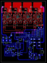
What do you think of my circuit? (BMS A123 x12 eng.pdf)
A model with only 4 cell without lowvoltage is in test... (circuit board 4xA123)
Best regards,
Silicium
Hi, I'am a newbee in Endless Sphere and my english is very bad :-(
I make a BMS for a battery A123 (4P12S)...
What do you think of my circuit? (BMS A123 x12 eng.pdf)
A model with only 4 cell without lowvoltage is in test... (circuit board 4xA123)
Best regards,
Silicium
Attachments
Jozzer
100 kW
Welcome Silicium, and good first post!
how does it work?
I think we have some french speaking techie's onboard who will help with language barrier.
how does it work?
I think we have some french speaking techie's onboard who will help with language barrier.
GGoodrum
1 MW
Yes, welcome.
This thread is all about a123-based solutions, so it is definitely the right place. I'm trying to figure out how it works, but I think I will have to leave it to the experts here who are a little bit less electronically-challanged. It appears to stop the charging when all the cells reach some point?
Is this mainly a charger-balancer design, or is it intended that the circuits are co-located with the cells/pack? If the latter is true, is their any sort of low-voltage protection?
-- Gary
Salut ! Si t'a besoin d'aide avec l'anglais, je peux t'aider avec des traductions !
Welcome to the forum !
a good BMS is something we desperately need on here.. please tell us more !
Thanks !
Welcome to the forum !
a good BMS is something we desperately need on here.. please tell us more !
Thanks !
Malcolm
10 kW
fechter said:You might want to put some load on it when you are adjusting it.
There should still be a way to trim it lower.
Thanks for the advice Richard. I owe you a pint.
Had another go, this time soldering in a second 5k trim pot on the other side of the original trim pot. It worked! I've now got a 30A power supply with an adjustable output voltage of around 2.9 to 4.2 volts. Tried charging a 10p pack that was already at 3.25V. At a charging voltage of 3.75V the pack started charging at around 5A. Over the next half hour or so the current gradually tapered off to 0.3A. Disconnected the pack and it's now sitting at 3.62V. Looks like I can just connect the power source via a timer and set it to roughly the charge time I need.
Doctorbass
100 GW
Bonjour et Bienvenue Silicium!
Làje te parle en tant que ton cousin du Québec!
Ton circuit semble très prometteur! Félicitation!
Tiens nous au courant des tests et surtout si tu réalise un pcb pour 12 ou 16 cells... On pourraient faire du troc! je dispose de plusieur cell A123 pas cher! :wink:
Dis donc, est-ce que tu voiendrais par hazard du forum velectris? ou autre?
Je connais pas beaucoup de forum de vélo electrique en français...
Translation:
Your circuit seems very onteresting congrat!
Give us some news about an eventual PCB for 12 or 16 cells we could make some exchange.. i have some cheap douzen of A123 cells...
I wounder if you could come from the Velectris forum? or another like that... i onlu know few french furum about ebike...
Doc
lawsonuw
1 kW
Nice looking schematic and PCB layout.
Is there any reason why the outputs of the TCM809's in the schematic are not multiplexed onto the opto-couplers used for the voltage clamper? Is this to save current draw on the discharged cells? (see my post on back on page 5 of this thread for what I mean about multiplexing)
Nice idea including the charger into the BMS board. Lots easier to get everything working together this way. Why not use a variation of This circuit as the charge current source? It has it's limits, but for a PWM constant current supply this circuit is about as simple as it gets.
Marty
silicium
10 W
Bonjour àtous, votre accueil me fait chaud au coeur !
merci àYpedal pour son offre de traduction et rebonjour àDoctorbass qui m'avait passé des liens sur le forum Vélectris, pour le pcb, c'est sur, je ferai volontier du troc, mais je ne cablerai que ma carte...
@GGoodrum: The circuits BMS A123 x12 are co-located with the cells/pack, the circuit board 4xA123 is only a charger balancer.
Original text is in french, translate down...
Fonctionnement du BMS:
Le BMS est intégré àla batterie.
Le chargeur se branche sur J6-J7 (48V pour 12 cellules)
La charge démarre en appuyant sur SW1 (àcoté du relais), le relais est activé et s'auto maintient, il se désactivera quand le signal FINCHARGE deviendra actif (12V).
La charge sera terminée quand toutes les cellules seront chargées (tous les optos coupleurs actifs) le circuit qui gère cela est appelé Stop charger (il faut que tous les signaux FINx soit à'0' pour que FINCHARGE='1')
La charge se fait à2,5A (pour l'instant, beaucoup plus est envisageable...), mais cela entraînera une dissipation importante dans les transistors ballasts d'équilibrages (les MJD122), 3,6 x 2,5 = 9W !.
Pour réduire cette dissipation inutile, l'intensité de charge est abaissé à0,5A dès qu'une cellule arrive àl'équilibrage. Le circuit a diode àgauche du schéma détecte qu'une cellule est chargé et agit sur le générateur de courant pour limiter celui-ci à0,5A, soit 0,5 x 3,6= 1,8W.
Cette baisse du courant ne devrait pas beaucoup allonger la durée de charge car si une cellule est chargée, les autres n'en sont pas éloignée...
Quand la charge est terminée (toutes les cellules à3,6V donc tous les optos actifs), le relais est désactivé et le 48V/3A peut être débranché.
La partie générateur de courant et relais aurait pu être mise àl'extérieur mais cela aurait fait encore trop de fils entre le chargeur et le pack àmon goût...
La protection des cellules àla décharge est fait par les circuits TCM809Z avec une coupure à2,3V. Je n'ai pas utilisé l'opto coupleur pour ne pas consommer trop d'intensité sur une cellule déjàvide ! Si on allume une led pour dire que la cellule est vide, on va la vider encore plus !
Le circuit prélève environ 100 uA sur une cellule vide. Si une cellule est vide, c'est le signal CTRLOFF qui passe à0, celui-ci agit comme la poignée de frein du vélo, en coupant le contrôleur.
La consommation du bms est d'environ 40uA sur une cellule, pas de risque donc de vider le pack ! (2300/0.04=2400 jours...)
Je teste le circuit avec 4 cellules, ce petit chargeur n'est pas intégré àla batterie, il sera utilisé pour chargé des packs 4S utilisé dans un robot (ces packs ont un circuit de protection àla décharge voisin du circuit décrit sauf qu'il y a un mosfet qui coupe le pack, je donnerai le schéma/typon si cela vous intéresse)
Translate soon: (spécial thank's Ypedal)
The BMS is integrated into the pattery pack.
The charge cycle starts by pushing SW1 ( Next to the relay ), this activates the relay and it auto-maintains and remains active until FINCHARGE (end of charge ) reaches 12v.
The charge cycle ends once all the opto-couplers become active, the circuit that controls this is called 'stop charger' (all signal FINx equal '0' for FINCHARGE='1')
For now, the charge rate = 2.5 amps, this requires a substantial heat disipation within the ballancing MJD122 transformer ballasts of 9w.
a higher charge rate is planned for the future !!
As soon as the first cell reaches full charge, a Diode circuit on the left of the schematic reduces the current to 0.5 amps to reduce heat disipation,
This current reduction should not extend the charge time considerably, if one cell is fully charged, the rest are not far behind.
Once all the cells are at 3.6v, and the opto's active, the relay is disactivated and the 48v/3amp can be disconected.
The power generator and relay could have been external, but this would have added too many extra wires between the charger and the pack for my personal taste.
The cell protection is done via TCM809Z with a 2.3v cutoff, I have did not use Opto couplers for this to avoid drawing power from an already drained cell, if we light an LED to flag a dead cell we only drain it more..
The circuit only consumed 100 ua (micro) on an empty cell, if one cell drops below cut-off, the CTRLOFF singnal goes = 0 and acts like a brake cut-off on the controller ( just like Bob's and Ggoodrums lvc setup ! )
The BMS only consumes 40ua on one cell, no risk of draining the pack as this would take 2400 days.
I am testing this 4 cell circuit, , it is used to charge 4 S packs in a robot,
currently not integrated to the pack as there is a seperate LVC circuit already in there, only difference is that there is a mosfet to disconect the pack, i can share this if you all like === YES !!
Best regards
Silicium
Similar threads
- Replies
- 2
- Views
- 98