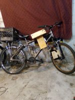
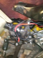
I am having second thoughts about a second identical front hub. Not only is the wiring for single display and throttle for two hub motors problematic, suspension forks are not suitable for a 1,500 watt motor even if I start off with pedal and assist level 1.
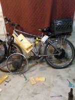
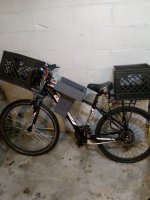
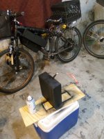
The bike as is with the rear hub is very smooth and easy to control from 0 to > 30 mph with 5 assist levels. The only reason for a second motor is steep hills and maintaining > 30 mph for an extended period of time.
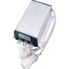
One solution that most ebike builders would do is simply order a 45 amp controller 18 mosfet controller to replace the wimpy 30 amp that probably has 12 or less mosfets. However anyone who knows me will tell you I do not always choose the simple and obvious way.
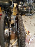
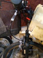
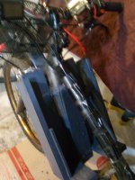
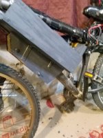
A front fork chain drive 1,000 watts or greater and 30 amp brush controller geared for about 32 mph could give a little boost up hills and share the load and heat generated at 30 mph cruising for an extended period of time. Also it will be as simple as switching on a 40 amp DC breaker and engaging a left thumb throttle.
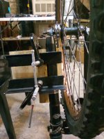
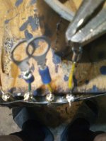
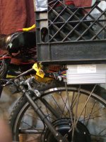
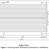
The hard part will be the welding but the picture below shows how it has already been done. If I have to pay someone who can weld then the rest will be fairly straightforward. I still can not seem to post youtube links here. I did figure out how to post pictures though and provided the name of the you tube video and channel.
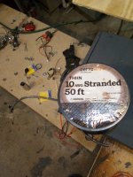
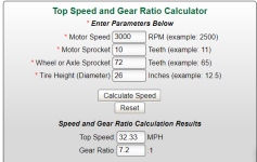
A 10 tooth 8mm sprocket and 72T wheel gives 32 mph gearing for the chain drive.

Dorky Thorpy
Hope to hear from some of you on this.
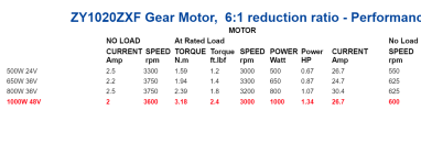
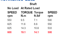
Looking at specifications I may need a smaller freewheel like a 14T for around 30 mph gearing as 600 rpm is zero load and 500 rpm recommended load. What I really do not understand though is the torque specs.
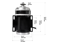
For example the 1,500 watt rear hub motor has Motor Torque: 74.5 N.m
The 1,000W brush chain 19.1 N.m
I do know that gearing for a chain drive motor will change that number but do not know the formula for that.
With a 14T freewheel the 1,000W chain should do.

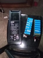
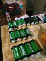
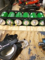
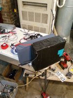
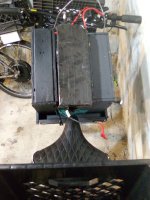
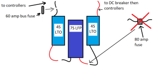
That is actually better than 32 mph torque wise and hills. Top speed is not important in this build. It is about hill climbing ability and maintaining 28 to 30 mph cruising for an extended period of time without overheating either motor or controller. Since Lishen LTO batteries will be used we can rule the batteries out as a weak link as they are good for 400 amps continuous.
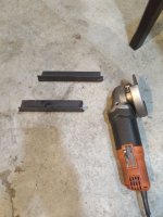
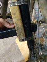
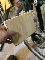
Welding would be more logical however my welder is not here as it is somewhere else and I have no idea how to weld. Also if I manage to pull this off then anyone who reads this can copy it and mount a front chain to about any front fork. Building materials have about doubled in the last 10 years or so. I happen to have steel bed frame lying around in the basement. I will need at least 1/4" bolts grade 8. It is work in progress.
Skyler.


The bike as is with the rear hub is very smooth and easy to control from 0 to > 30 mph with 5 assist levels. The only reason for a second motor is steep hills and maintaining > 30 mph for an extended period of time.
One solution that most ebike builders would do is simply order a 45 amp controller 18 mosfet controller to replace the wimpy 30 amp that probably has 12 or less mosfets. However anyone who knows me will tell you I do not always choose the simple and obvious way.
A front fork chain drive 1,000 watts or greater and 30 amp brush controller geared for about 32 mph could give a little boost up hills and share the load and heat generated at 30 mph cruising for an extended period of time. Also it will be as simple as switching on a 40 amp DC breaker and engaging a left thumb throttle.
The hard part will be the welding but the picture below shows how it has already been done. If I have to pay someone who can weld then the rest will be fairly straightforward. I still can not seem to post youtube links here. I did figure out how to post pictures though and provided the name of the you tube video and channel.
A 10 tooth 8mm sprocket and 72T wheel gives 32 mph gearing for the chain drive.
Chain Drive Front Wheel Ebike
Dorky Thorpy
Hope to hear from some of you on this.
Looking at specifications I may need a smaller freewheel like a 14T for around 30 mph gearing as 600 rpm is zero load and 500 rpm recommended load. What I really do not understand though is the torque specs.
For example the 1,500 watt rear hub motor has Motor Torque: 74.5 N.m
The 1,000W brush chain 19.1 N.m
I do know that gearing for a chain drive motor will change that number but do not know the formula for that.
With a 14T freewheel the 1,000W chain should do.
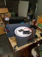
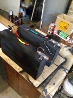
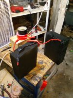
That is actually better than 32 mph torque wise and hills. Top speed is not important in this build. It is about hill climbing ability and maintaining 28 to 30 mph cruising for an extended period of time without overheating either motor or controller. Since Lishen LTO batteries will be used we can rule the batteries out as a weak link as they are good for 400 amps continuous.
Welding would be more logical however my welder is not here as it is somewhere else and I have no idea how to weld. Also if I manage to pull this off then anyone who reads this can copy it and mount a front chain to about any front fork. Building materials have about doubled in the last 10 years or so. I happen to have steel bed frame lying around in the basement. I will need at least 1/4" bolts grade 8. It is work in progress.
Skyler.
Attachments
Last edited: