The care and feeding of a123-based packs...

@Ypedal: je fais appel à toi pour traduire s'il te plait :wink:

Fonctionnement du BMS:
Le BMS est intégré à la batterie.
The BMS is integrated into the pattery pack

Le chargeur se branche sur J6-J7 (48V pour 12 cellules)
The charger connects to J6-J7 ( 48v for 12 cells )

La charge démarre en appuyant sur SW1 (à coté du relais), le relais est activé et s'auto maintient, il se désactivera quand le signal FINCHARGE deviendra actif (12V).
The charge cycle starts by pushing SW1 ( Next to the relay ), this activates the relay and it auto-maintains and remains active until FINCHARGE (end of charge ) reaches 12v

La charge sera terminée quand toutes les cellules seront chargées (tous les optos coupleurs actifs) le circuit qui gère cela est appelé Stop charger (il faut que tous les signaux FINx soit à '0' pour que FINCHARGE='1')
The charge cycle ends once all the opto-couplers become active, the circuit that controls this is called " stop charger ", ( Fin = end not sure how to translate this part without causing confusion)

La charge se fait à 2,5A (pour l'instant, beaucoup plus est envisageable...), mais cela entraînera une dissipation importante dans les transistors ballasts d'équilibrages (les MJD122), 3,6 x 2,5 = 9W !.
For now, the charge rate = 2.5 amps, this requires a substantial heat disipation within the ballancing MJD122 transformer ballasts of 9w.. a higher charge rate is planned for the future !!


Pour réduire cette dissipation inutile, l'intensité de charge est abaissé à 0,5A dès qu'une cellule arrive à l'équilibrage. Le circuit a diode à gauche du schéma détecte qu'une cellule est chargé et agit sur le générateur de courant pour limiter celui-ci à 0,5A, soit 0,5 x 3,6= 1,8W.
As soon as the first cell reaches full charge, a Diode circuit on the left of the schematic reduces the current to 0.5 amps to reduce heat disipation,

Cette baisse du courant ne devrait pas beaucoup allonger la durée de charge car si une cellule est chargée, les autres n'en sont pas éloignée...
Quand la charge est terminée (toutes les cellules à 3,6V donc tous les optos actifs), le relais est désactivé et le 48V/3A peut être débranché.
This current reduction should not extend the charge time considerably, if one cell is fully charged, the rest are not far behind.

Once all the cells are at 3.6v, and the opto's active, the relay is disactivated and the 48v/3amp can be disconected.


La partie générateur de courant et relais aurait pu être mise à l'extérieur mais cela aurait fait encore trop de fils entre le chargeur et le pack à mon goût...
The power generator and relay could have been external, but this would have added too many extra wires between the charger and the pack for my personal taste

La protection des cellules à la décharge est fait par les circuits TCM809Z avec une coupure à 2,3V. Je n'ai pas utilisé l'opto coupleur pour ne pas consommer trop d'intensité sur une cellule déjà vide ! Si on allume une led pour dire que la cellule est vide, on va la vider encore plus !
The cell protection is done via TCM809Z with a 2.3v cutoff, I have did not use Opto couplers for this to avoid drawing power from an already drained cell, if we light an LED to flag a dead cell we only drain it more..


Le circuit prélève environ 100 uA sur une cellule vide. Si une cellule est vide, c'est le signal CTRLOFF qui passe à 0, celui-ci agit comme la poignée de frein du vélo, en coupant le contrôleur.
The circuit only consumed 100 ua ( micro or milli ? ) on an empty cell, if one cell drops below cut-off, the CTRLOFF singnal goes = 0 and acts like a brake cut-off on the controller ( just like Bob's and Ggoodrums lvc setup ! )

La consommation du bms est d'environ 40uA sur une cellule, pas de risque donc de vider le pack ! (2300/0.04=2400 jours...)
The BMS only consumes 40ua on one cell, no risk of draining the pack as this would take 2400 days.


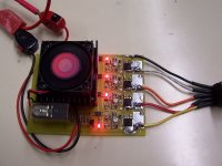
Je teste le circuit avec 4 cellules, ce petit chargeur n'est pas intégré à la batterie, il sera utilisé pour chargé des packs 4S utilisé dans un robot (ces packs ont un circuit de protection à la décharge voisin du circuit décrit sauf qu'il y a un mosfet qui coupe le pack, je donnerai le schéma/typon si cela vous intéresse)
I am testing this 4 cell circuit, , it is used to charge 4 S packs in a robot,
currently not integrated to the pack as there is a seperate LVC circuit already in there, only difference is that there is a mosfet to disconect the pack, i can share this if you all like === YES !! :wink:


Encore merci pour votre accueil, j'ajouterai la traduction en anglais si Ypedal est courageux :lol:

A bientôt[/quote]
 
Thanks for the explanation, and the translations. I'm still a bit confused, but then again, I'm always confused. :) Does this circuit implement a typical CC/CV-typ charging profile, where the cells are held at the cutoff (3.7V?) as the current is gradually reduced, or does it simply cut the charging off for that cell once the voltage reaches the cutoff? Also, what would have to be changed/added in order to allw charging at a higher rate? At 2.5A, it will still take quite a while to do a 10Ah pack.

-- Gary
 
I'm a big fan of keeping things as simple as possible. The controller already has the brake inhibit signal that can be used to cut power, so using the simplified LVC circuit to use this existing capability if a cell voltage drops too low makes perfect sense to me. Having a FET for absolute cutoff for each block, like some of the designs I've seen, seems wasteful.

On the charging/balancing end, I also think simple is better. The absolute best way I've found so far to ensure each cell block is fully charged is to use individual CC/CV chargers. With all of the shunt-type balancers I've seen in the RC world, they usually work by draining off the higher voltage cells/cell blocks to whatever the lowest one is at. If there is a cell, or cell block that has less capacity than the rest, it means all the cells will not necessarily reach their full potential. Individual cell charging lets each block reach its max capacity.

I've been using the 10-cell setup, shown below, for awhile now, and I'm very happy, except for the fact that it does take longer than I'd like, if the packs are more than half-drained.

10-cell%20a123%20Charger-Balancer.jpg


One of the real advantages that a123-based setups have over pretty much everything else out there, is that they can be safely charged at very high rates, like 20-30A, and that is for a single cell. For a 4p configured pack, that is 80-120A. :shock: Now that isn't really practical, but certainly 20A is "doable". What I decided to do was to still use the 2A individual cell CC/CV chargers, but initally at least, add a 37V/20A "booster" supply for the heavy lifting. I found several 0-40V 20A surplus supplies on eBay for around $150, or less.

The problem is, how to shut off the boost supply when the pack gets to about the 85-90% point. With some help from Bob, this is what I came up with:

10-Cell%20Boost%20Charger%20Circuit-v%201-2.png


Basically, a FET is used to shutoff the 37V/20A boost supply as soon as any one of the cell blocks hits 3.7V. The thinking is that once one cell first hits the cutoff voltage, the rest are not far behind. At that point, the cells are close to 90% full. Once the boost supply is cutoff, the individual cell chargers continue on to "top-off" and balance the cells.

10-Cell%20Charger-Booster.png


To detect the 3.7V cutoff, I'm using a modified version of the LVC circuit. A pair of resistors are used as a voltage divider to drop the input down a bit, and then fed into the TC54 chip, whose output is then connected to the input of the optocoupler via a current limiting resistor. Normally, this chip is used to detect when a voltage drops below a certain point (2.7V for this version...), but here it is being used to detect a high point. Once the input voltage, through the divider, reaches 2.85V (2.7V + .15V for hysterisis...), the TC54 goes high, which turns on the optocoupler. The divider resistor values are chosen so that 2.85V at the input of the TC54, is about 3.7V at the cell. The opto outputs are all ganged together and are connected to the gate control for the FET. Normally, the pullup resistor and the 5.1V zener keep the FET on, which allows the bosst supply to be connected to the main pack leads, but if any of the optos trip, the zener is bypassed, and the FET cuts off.

The board has inputs for each of the 10 single-cell chargers and two outputs for the standard RC-style balancer plugs that I'm using on my 10s4p packs. With the 20A booster, I should be able to cut the amount of time it takes to fully charge and balance a depleted 10s4p pack down to well under an hour. :)

-- Gary
 
Thats quite a post considering it started with the phrase " I like to keep it simple" :lol:
 
That looks like it should work. The hysteresis should hopefully keep it from going into oscillation when the first cell reaches the trip point. If you want it to latch, you could add a SCR to shunt the zener.
 
Jozzer said:
Thats quite a post considering it started with the phrase " I like to keep it simple" :lol:

Well, the circuit is pretty simple, but the explanation is a bit verbose. :lol:

I could've added ways to "latch" the output, so that once off, the 37V supply remains off, but that would require more parts and a pushbutton. With this design, the power for the gate control logic comes directly from the bosst supply. There is a chance that once a cell first hits 3.7V, and the boost supply is cut, the cell could dop below the cutoff, causing the boost supply to be switched on again, but I think this is fine. The individual cell charger will help keep the voltage up, so if it does happen, it won't be more than a few times. This type of "pulsing" is actually how the AstroFlight RC chargers work in the final phase. It pulses the cells at someting close to full current and checks the "resting" voltage in between pulses. When the voltage stays above the cutoff for 10 seconds, the process is stopped.

-- Gary
 
fechter said:
That looks like it should work. The hysteresis should hopefully keep it from going into oscillation when the first cell reaches the trip point. If you want it to latch, you could add a SCR to shunt the zener.

Yes, you are right, but I'm going to try it without the latching first, for the reasons I stated above, and see how it does.

The only thinkg left to do, in my quest for simplicity, is to have an integrated charging cable/connector, so that only one connection is required. I saw some 25-pin size D-Sub connectors at Mouser that have two big pins and 17 little ones: http://www.mouser.com/catalog/632/1099.pdf. With one of these you could have up to a 16-cell pack with a single connector that could be used for charging. Just come back from a ride, plug in the charging system, and then come back in about an hour. That's the holy grail of setups for me. :)
 
Those look like nice connectors.
The other approach I've seen is to parallel a bunch of small pins for the high current stuff and just use a regular 25pin connector.

I agree that a single plug for charging is very desirable.

If the circuit oscillates at a low frequency, that might be OK. My SLA charger behaves like that. You can tell how close to full charge you are by how fast it's blinking.
 
fechter said:
Those look like nice connectors.
The other approach I've seen is to parallel a bunch of small pins for the high current stuff and just use a regular 25pin connector.

I agree that a single plug for charging is very desirable.

If the circuit oscillates at a low frequency, that might be OK. My SLA charger behaves like that. You can tell how close to full charge you are by how fast it's blinking.

I hadn't thought of that, but there's tons of old printer and serial cables out there. How many pins would you need to handle 20A?
 
printer and serial cables are only rated to take an amp per pin so they would probably not be a very good choice.

somebody mentioned that you could reduce the standby current by increasing the value of the resistors used to move the trigger point for the TC54 on channels where a different voltage is required. I chose the values to provide 100x the bias current of the TC54 so that the bias current would not cause an error over 1%. if you increase the resistors 10x you will increase the error 10x.
 
Ypedal said:
IDE hard drive cables the same gauge as printer wire ?

smaller - typically they are 30 gauge and the ide connectors they use are not good for more than an amp
 
One of these should do. (Parallel yer arse off.)

winchester7.jpg

http://cdmelectronics.thomasnet.com/item/nchester-electronics-rack-and-panel-connectors-xac/-external-miniature-rectangular-removable-contacts/xac50p?&seo=110
 
Hi everybody. This is my first post on endless. I've been reading this post for a while.The drag bike called Killacycle uses a123 batteries and a manzanita charger that can charge the pack up 80% in like 5 min. or something. What kind of BMS are they using?Maybe we could apply a similar BMS to the DeWalt packs?
 
Daniel828 said:
Hi everybody. This is my first post on endless. I've been reading this post for a while.The drag bike called Killacycle uses a123 batteries and a manzanita charger that can charge the pack up 80% in like 5 min. or something. What kind of BMS are they using?Maybe we could apply a similar BMS to the DeWalt packs?

Hi Daniel, and welcome. :)

It is hard to say what they have right now. I know they have modules that handle something like 5 cells. I think the latest configuration is something like 110 cells in series and 11 in parallel. Our setups are obviously a fraction of this beast.

There are two big issues with any setup. One is protecting the cells from being over-discharged, and the other is having each cell get a full charge. The trick is coming up with solutions to both that aren't too complicated. The over-discharge problem is handled by some BMS units with an active cutoff of a block of cells, if the voltage drops too low. For our ebike setups, the controllers have an input that can be tripped to have the controller cut power if any cell/cell block drops too low. This really simplifies this portion of the BMS.

The second issue, how to fully charge each cell, is a tougher nut to crack. Basially, you have two choices, either have a complicated balancer circuit, which usually means some sort of shunt regulator, which generates lots of heat that has to be dealt with, or you do the balancing external to the pack, but this means bring out a bundle of wires for the cell junctions. Neither is the ultimate right answer, in my opinion, but the lesser of two evils is to bring the wires out, I think. With multiple independent cell chargers, you can at least ensure that the cells are alwaays fully charged/balanced. This also simplifies the BMS down to where you only need a very simple circuit that monitors the voltage of each cell/cell block, and trips the cutoff line to the controller if the voltage for any cell drops too low (about 2.7V...).

The holy grail of setups for me is to have a way to charge packs at a fairly high rate (15-20A...) but end up with fully charged cells, and not have to use shunts or have to bring out a messy bundle of wires. I'm not there yet, but I'm not giving up until I do. :)

-- Gary
 
In the search for the holy grail, one could use an inductive switcher of some sort to balance on charge without dissipating the excess. Perhaps something similar to the PowerCheq, only made for Li.

A switched capacitor balancing scheme might work also.

Both of these solutions would be fairly complex and expensive. In mass quantities, they might not be too bad.

Still searching.....
 
fechter said:
In the search for the holy grail, one could use an inductive switcher of some sort to balance on charge without dissipating the excess. Perhaps something similar to the PowerCheq, only made for Li.

The trick with any of the switching power supplies is that they take power from one supply and change the voltage or current to adapt it to a load. The current per-cell shunt circuits just take the excess power from the cell and it doesn't have anywhere to put the excess power so this excess power is dissipated as heat. If the voltage limiter for the cells now covers two cells it's a different story. Now a Buck-Boost style DC-DC converter can be built to take excess current from one cell and add it to the current in the second cell. Further, if these two-cell voltage limiters/ballancers are overlapped in a series string, excess energy can be passed from the strong cells to the weak cells in a battery pack. (if the Diode in the buck-boost converter is replaced with a MOSFET it becomes symetrical and can throw energy bi-drectionally from cell to cell)

The PowerCheq is a really cool porduct. It looks like it's primarily aimed at the traction and backup power lead-acid market. But no reason it couldn't be adapted to Lithium chemistries. The company is in my "back yard" and in the Motive .pdf they describe it's use in a simulated scooter. Couldn't find any price for it though. It should be worth while to bug them for when a Lithium version will be coming out.

Marty
 
I tested the charging circuit and protection for 4 cells A123.
The protection circuit is working properly and also the charger.
On the image 101_0064.JPG, 3 cells on 4 are charged.
I now preparing the final schematic for managing 12 cells in series. The scheme given above should be altered, there are errors ...
The monitoring of the discharge cells also necessity to some modifications, monitoring circuits is quite sensitive ...
Otherwise, I tested the discharge Pack 4 cells at 9A, it résist 14 minutes and 30 seconds ... Keeping Promises!
 

Attachments

  • 101_0064.JPG
    101_0064.JPG
    66.3 KB · Views: 5,234
Good work Silicium, keep us updated! Do you mind if we use your circuit on our packs?
 
lawsonuw said:
@Silicium: just an FYI I found this low input current opto-isolator on Digi-key

Digi-Key link http://search.digikey.com/scripts/DkSearch/dksus.dll?Detail?name=516-1681-5-ND
(they have an 8-dip dual channel version in stock)

Data sheet http://www.avagotech.com/assets/downloadDocument.do?id=1743
This part specs that it needs only a 40uA input current to work, and has a fairly high current transfer ratio.

Yes ! It's good product. It's ok for use a opto in monitoring discharge cut off.
Price is 5 $ for dual opto, 5x6=30 $ for 12 cells
 
Hi, everybody from Germany for my first post at Endless!
I am also interested about BMS developed by Silicium.
It should do the entire job to manage A123 battery pack (cut-off at low and high voltage, balancing at the end of charging) with a standard charger.

I have planned to perform one with A123 battery when it will be release…
Then, I have discussed today with him about some trouble must be solved…:roll:
At the end of charging, when, BMS is starting to equilibrate cells. There is “smallâ€￾ current oscillation in both direction between BMS and cells already full.
Silicium would like to cancel these oscillations. He has tested with one inductance between cells and BMS, but it’s become more critical!
With a bigger cable between BMS and cells, this phenomena is decrease.
He thinks…we must introduce a filtering (R,C) somewhere…!
How to solve this problem?

In order to assembly BMS with battery without risk of over eating the battery.
I have proposed to them to externalise the 2,5A current limit controller in order to have no heating during first phases of charging.
BMS will keep only the current limit function for balancing the cells (500mA). Perhaps, it also too much! Does 100mA enough?
This will also offer possibility to charge the battery with higher current (depending of the charger possibility).
 
Yes, if the current source is external, heat is also external... For 8A current charge and 12 cells in serie, cell voltage min is 3x12=36V and cells voltage max is 3.6x12=43.2V. For correct constant current at 0.5A (balancing) the voltage min for the power source is 46V. At 8A, the power dissipation max is (46-36)x8=80W... External heat is desirable...
I will receive a power switching 48V/400W (8.3A) :) So I anticipate a load to 8A :D
 
lawsonuw said:
fechter said:
In the search for the holy grail, one could use an inductive switcher of some sort to balance on charge without dissipating the excess. Perhaps something similar to the PowerCheq, only made for Li.

The trick with any of the switching power supplies is that they take power from one supply and change the voltage or current to adapt it to a load. The current per-cell shunt circuits just take the excess power from the cell and it doesn't have anywhere to put the excess power so this excess power is dissipated as heat. If the voltage limiter for the cells now covers two cells it's a different story. Now a Buck-Boost style DC-DC converter can be built to take excess current from one cell and add it to the current in the second cell. Further, if these two-cell voltage limiters/ballancers are overlapped in a series string, excess energy can be passed from the strong cells to the weak cells in a battery pack. (if the Diode in the buck-boost converter is replaced with a MOSFET it becomes symetrical and can throw energy bi-drectionally from cell to cell)

The PowerCheq is a really cool porduct. It looks like it's primarily aimed at the traction and backup power lead-acid market. But no reason it couldn't be adapted to Lithium chemistries. The company is in my "back yard" and in the Motive .pdf they describe it's use in a simulated scooter. Couldn't find any price for it though. It should be worth while to bug them for when a Lithium version will be coming out.

Marty

Well, the math in the buck, boost and buck-boost circuit descriptions in the Wikipedia link made my brain hurt. :shock: Interesting stuff, but I can't make the leap to see how something like this can be used to do what the PowerCheq does, which seems like exactly what we need. Even if they did have a price listed, it won't work with single Lithium-based cells. The idea is great, though. How does it work?

-- Gary
 
Back
Top