Getting_Dave
100 µW
- Joined
- Aug 13, 2020
- Messages
- 8
Hello there and thank you for your time.
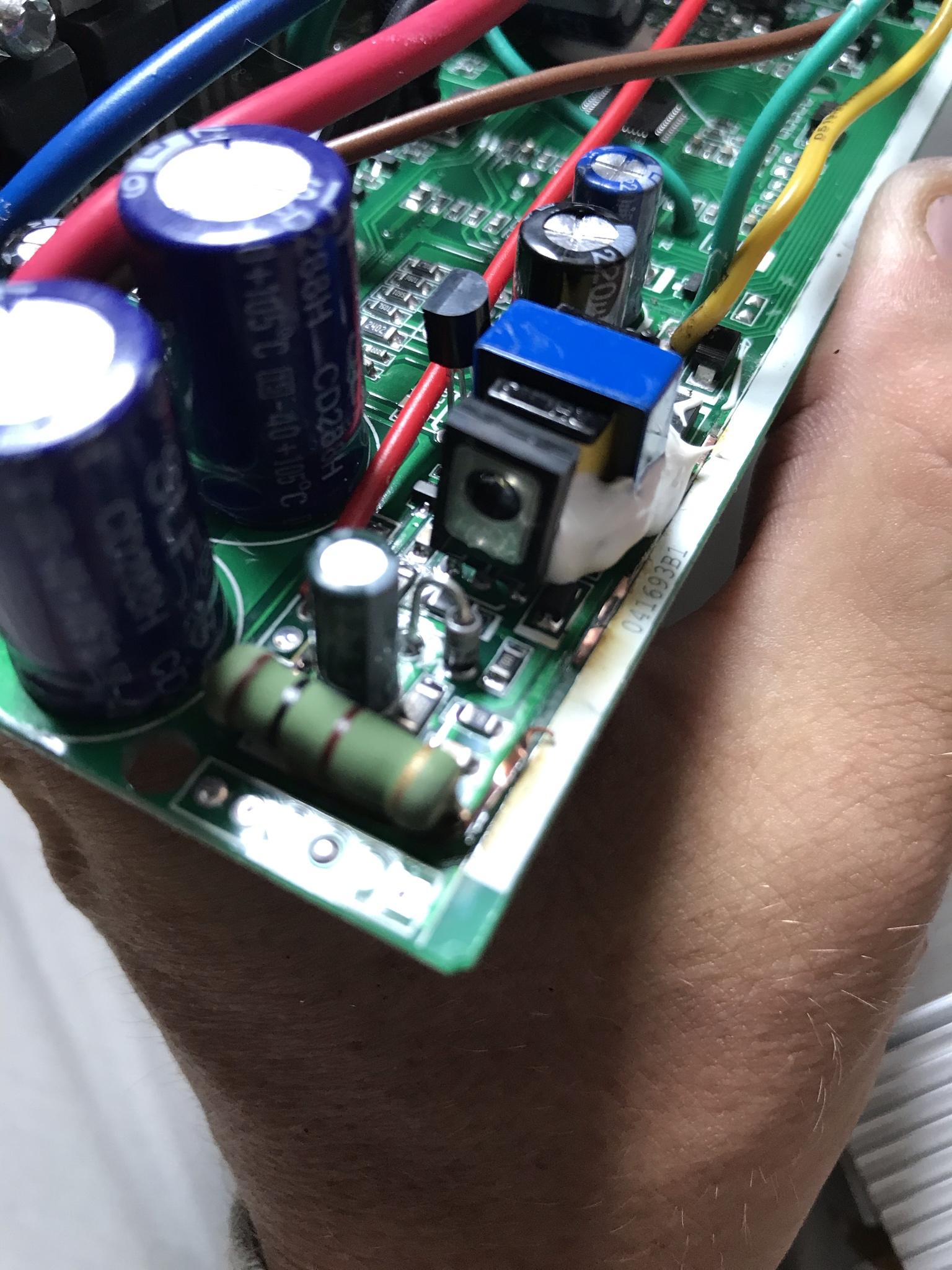
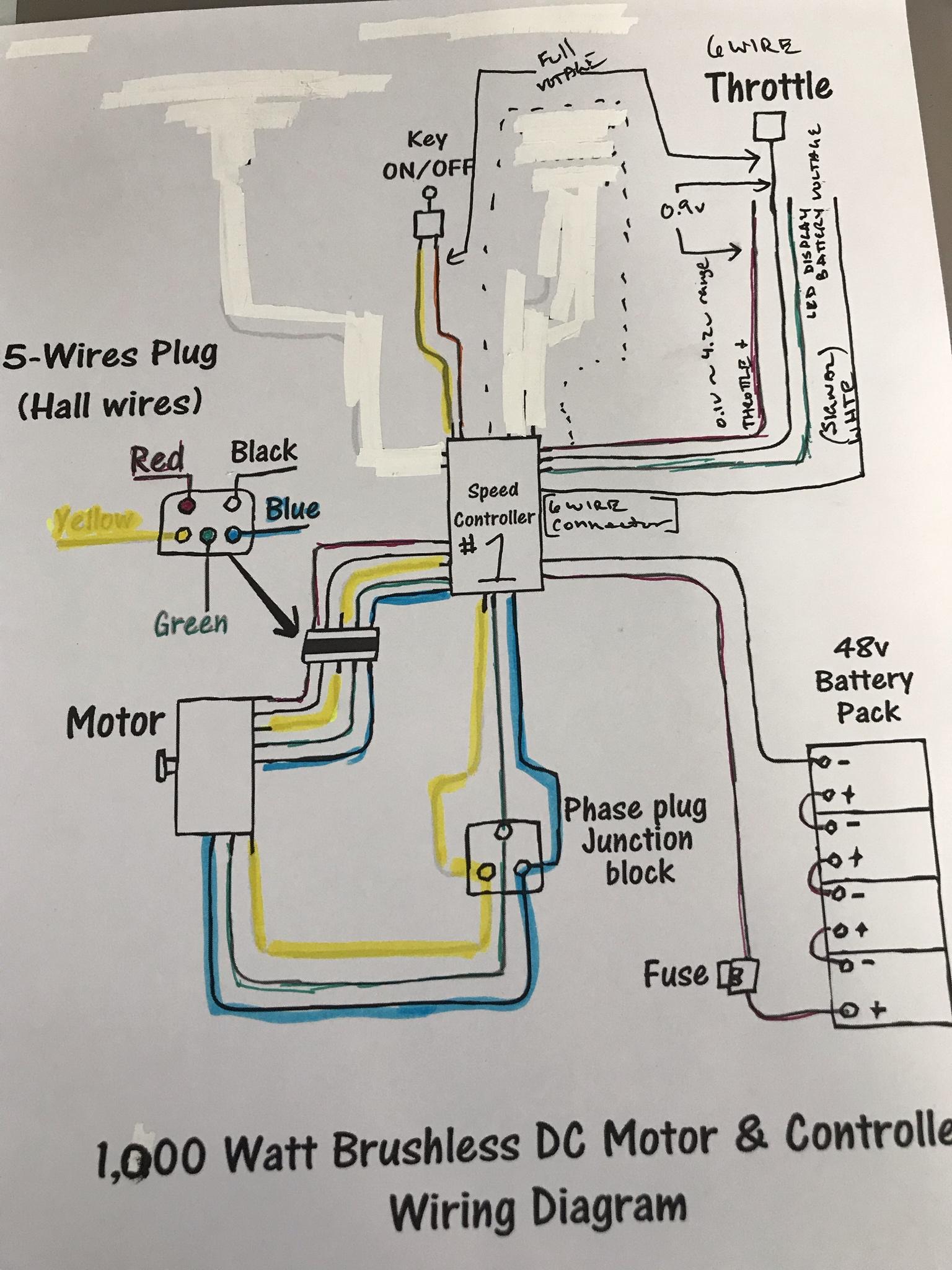
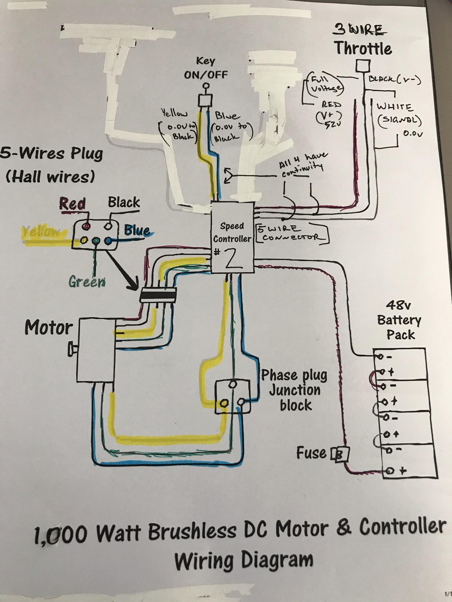
What I have is a 48v 1000w controller and a 48v 1000w front hub motor on my bicycle. I have had an issue with the half twist throttle where it lights up, has an on/off switch but it doesn’t send signal.
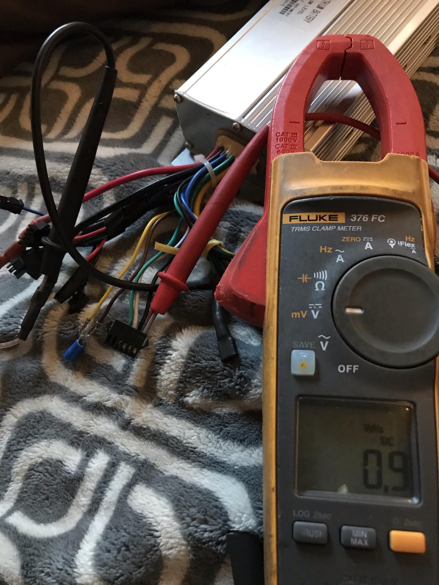
I ran a test with a fully charged 18650 @ 4.2 v to check the hall sensor. It was showing full voltage across +v and -v with the signal 4.1v. This is true for the second throttle I purchased as well. The hall sensor testing at low voltage from +v to signal doesn’t change when the throttle is twisted.
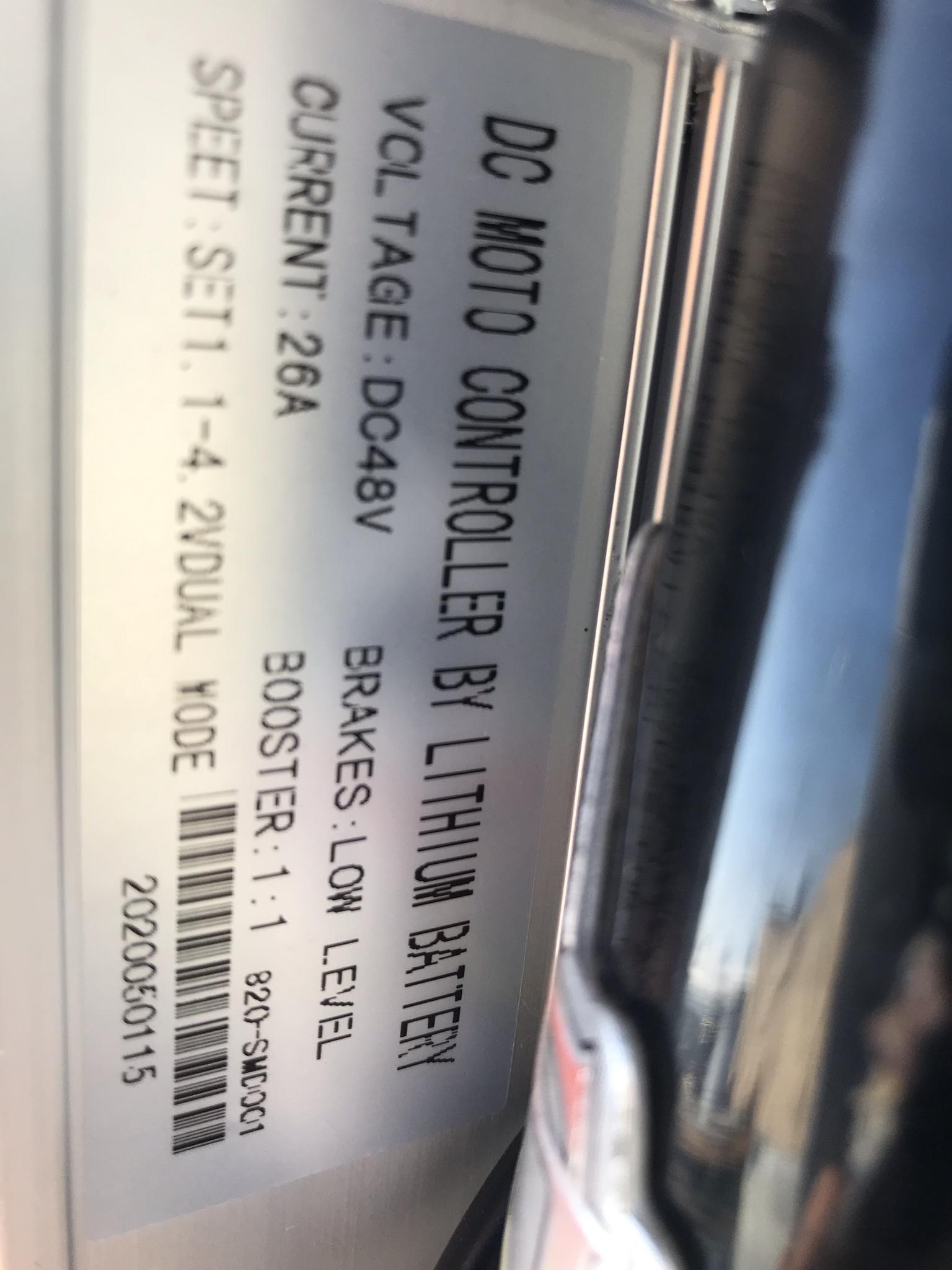
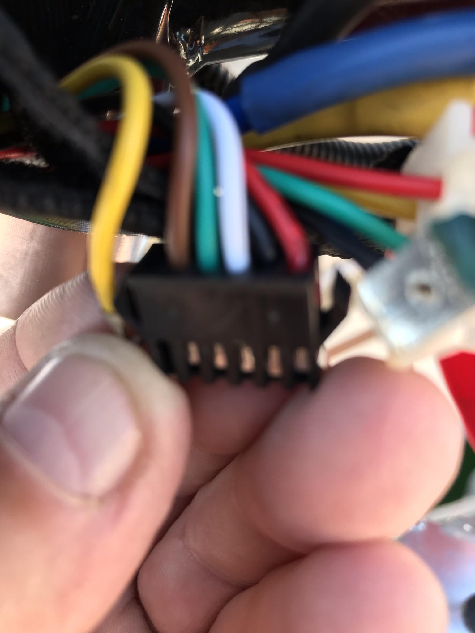
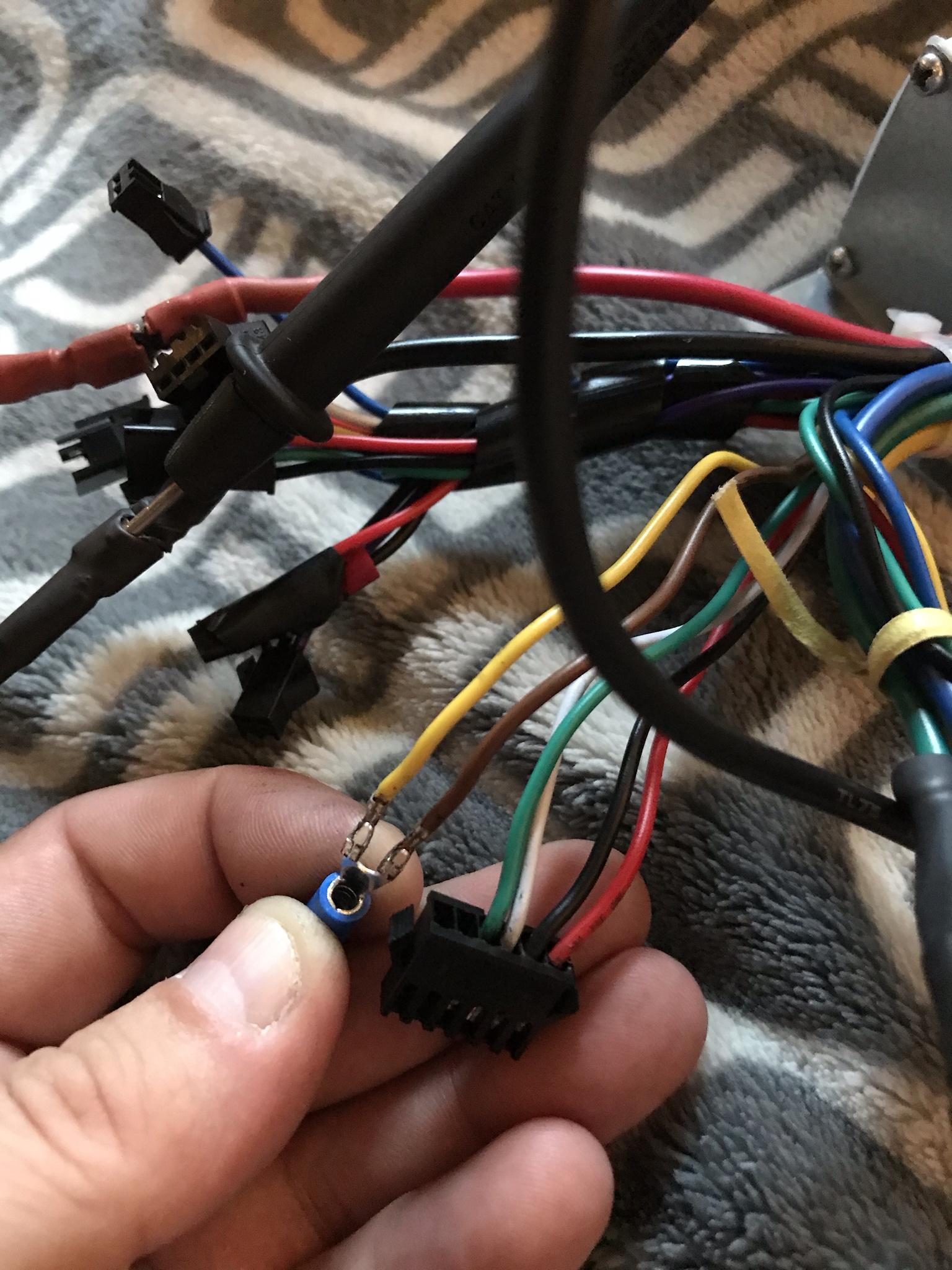
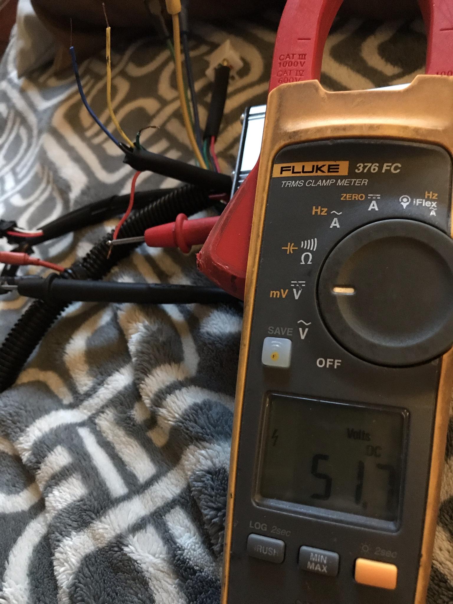
From the controller I have a 51v output into these throttles. I took apart one of the throttles and found a resistor on the signal wire it seems attached to the hall sensor directly.
I can only find operating voltage of 5v. Some how I have two speed controllers that are both outputting out 52v.
So do I need a specific throttle, are the controllers bad or another test for these sensors.
Any help would be greatly appreciated.
What I have is a 48v 1000w controller and a 48v 1000w front hub motor on my bicycle. I have had an issue with the half twist throttle where it lights up, has an on/off switch but it doesn’t send signal.
I ran a test with a fully charged 18650 @ 4.2 v to check the hall sensor. It was showing full voltage across +v and -v with the signal 4.1v. This is true for the second throttle I purchased as well. The hall sensor testing at low voltage from +v to signal doesn’t change when the throttle is twisted.
From the controller I have a 51v output into these throttles. I took apart one of the throttles and found a resistor on the signal wire it seems attached to the hall sensor directly.
I can only find operating voltage of 5v. Some how I have two speed controllers that are both outputting out 52v.
So do I need a specific throttle, are the controllers bad or another test for these sensors.
Any help would be greatly appreciated.
")