• Howdy! we're looking for donations to finish custom knowledgebase software for this forum. Please see our Funding drive thread

Using RC motors on E-bikes [Archive]

Status
Not open for further replies.
What Would You Do?

Let's say that the RC motor development for ebikes continues to advance and people find that they can pump out 3000 watts of power from a motor that is only a few pounds. They then go to "prove themselves" at a racetrack for ebikes and the organization tells them that everyone uses a wattage restriction circuit that limits power output to a maximum of 1000 watts with no exceptions.

Now all the effort that was made to get this extreme power would be wasted as the rules of racing would not allow the full usage of the motors potential.

:?: Do you:

1. Skip racing altogether.

2. Try to get a new "unlimited power class" formed within the existing organization.

3. Form a new racing organization that has different rules than the one's using wattage restriction circuits.

4. Refocus your development efforts to reducing the motor to the minimun needed to build 1000 watts of power. (in other words to "go along" with the 1000 watt rule and yet still get the benefits of lighter weight)

...I'm just curious how people are likely to react to such a future situation. :)

Another factor is insurance... it's harder to get the go ahead for more powerful classes without an increase in insurance costs, so actually doing the more powerful classes might call for more money in entry fees.
 
recumpence said:
I would say very few people race. For those who do, it would be very easy to scale down a drive for 1000 watts using RC motors that would be very efficient.
So you essentially would "go along".

That's good.

It's probable that the RC motors would still win based on weight and efficiency so the issue is shifted to building the right bike for the right type of racing.

The ePower race "happened" at Portland last year, so it does exist, though very small so far. Most of us are so geographically separated from each other that we have no ability to even race each other on the street due to the lack of other riders. But hopefully ebikes will catch on more and this sport can grow. It's easier to be a motorcycle road racer and find someone to ride with than an ebike rider seeking the same. (just based on the numbers)
 
Tom Tom said:
What do you guys think about the astroflight brushless motors?

http://www.astroflight.com/pdfs/3210.pdf

Hi,

Now that we have a separate forum this type of question is (IMO) perfect for its own thread.

Six month's from now when someone else has a question about this motor the chances of finding it are much greater in its own thread than in the middle of a 100 page thread (not there yet but still growing).
 
dontsendbubbamail said:
HAL9000v2.0 said:
Slowly I am turning off the hub motors, they are just to heavy for off roar ride. Last night I spent 2 hours reading this interesting post and just got 1 idea. Will this work? On HXT outruner motor like this one --> http://www.hobbycity.com/hobbycity/store/uh_viewItem.asp?idProduct=5139 I like to attach on the axle perforated disc and 3 opto sensors and run it with kelly brushless controller. I think gearing should be 1:16 for 26" wheel?

I am using the 130 kv version of this motor and a 53-54. You can read about my experience with HobbyCity motors on my "Bubba's Experiment" thread. My experience says that their voltage ratings are over rated by about 12V and the bearings are junk. I think they are great for experimenting and jury is still out on how long they last. Using this motor constantly at 3kw would be a stretch and I would expect you to have heating problems.

Bubba

It seems you're using the 230 Kv version and the thread is located at http://www.endless-sphere.com/forums/viewtopic.php?f=6&t=5317&st=0&sk=t&sd=a&start=15 . I was looking on HobbyCity's community forum for your thread and couldn't find it... so that's why I'm providing it here. Very interesting thread! I've yet to read it and I recently acquired a very similar motor(A 200 Kv version with everything else being the same) and I'm using it in my scooter build, so reading about your experiences is going to be oh so instructive.

Edit: Nevermind, you switched to the 130Kv version of page 6. That thing looks large in comparison to the 230Kv version!
 
dirty_d said:
lol, no by "regular gears" i mean regular gears.

Don't you mean spur gears? Eh...heh... Okay, I know this is a bit late, but I saw the name in a catalog and thought I'd mention it.
 
Hi Safe,

safe said:
What Would You Do?

Let's say that the RC motor development for ebikes continues to advance and people find that they can pump out 3000 watts of power from a motor that is only a few pounds.

I think we are well past that!

  • Matt's Pletti runs about 7kw peak, although the price is too much for many of us.

    David (CNCaddict) said he is designing for about 9kw peak.

    Scott, using a relatively small motor, was running about 2.8kw peak.
 
But you didn't address the question...

"What would you do?"

...when your 9kw peak motor on your racebike gets restricted with a 1kw restriction circuit in order to qualify as an ebike for ebike racing.

My point was that as I'm seeing ebikes defined they will be somewhere in the 1000 watt range for peak power input. All this development into massive power output motors have two problems:

:arrow: 1. They can never be street legal because the Federal Law restricts power output in the US to 750 watts.

:arrow: 2. They will not even be able to race other ebikes at a track because there will likely be wattage restriction circuits. (that's the direction that race rules will probably go in)

So how would you deal with this situation?
 
safe said:
"What would you do?"

:arrow: 1. They can never be street legal because the Federal Law restricts power output in the US to 750 watts.


So how would you deal with this situation?


Says Mr. runs a bike faster than is legal in Missouri and the US.....

I don't think many people here are worried about the power they are putting on the bike- including you.


IF it was a race situation, you bet people would use the smallest motor available for the job. You wouldn't buy a 9kw motor for a 1kw race bike.
 
safe said:
But you didn't address the question...

"What would you do?"

...when your 9kw peak motor on your racebike gets restricted with a 1kw restriction circuit in order to qualify as an ebike for ebike racing.

My point was that as I'm seeing ebikes defined they will be somewhere in the 1000 watt range for peak power input. All this development into massive power output motors have two problems:

:arrow: 1. They can never be street legal because the Federal Law restricts power output in the US to 750 watts.

:arrow: 2. They will not even be able to race other ebikes at a track because there will likely be wattage restriction circuits. (that's the direction that race rules will probably go in)

So how would you deal with this situation?

Hi,

Well the question was based on the premise that its a future issue which isn't accurate. Motors even more powerful are available now.

But I would:
1. Like everyone else ignore street legal. Its not currently enforced and enforcement would be very difficult.

2. Not my concern. Zero interest in racing. But if I did want to race I would try to use the lightest most reliable 1kw motor available, probably in conjunction with a Rohloff.
 
I've been playing around with outrunner brushless RC motors trying to get familiar with them and their quirks, prior to using an array of motors for an EV project. As I needed a new spindle motor for a home-built CNC machine, I thought it'd be an ideal opportunity to play around with a motor and controller.

I built the spindle OK, from an ER16 collet chuck and some bearings, and decided to direct drive it from a 550 watt rated outrunner. As this was a simple experiment, I didn't want to waste money on expensive smoke producing parts, so I went for a Turnigy motor and a 40 amp simple ESC. The power supply is limited to 29 amps at 12V, so I thought this should be OK.

What I've found is that the motor is fine, it spins up the chuck OK and doesn't get even slightly warm. The ESC gets pretty hot though, far too hot to touch when the motors running off-load at low speed. I've cut away the heatshrink around the controller and clamped it to a bigger finned heatsink, with some heatsink compound, but the motor wires particularly still get pretty warm and the heatsink heats up pretty quickly, even though the no-load curent is only around 4 to 5 amps at the mid-speed where it gets hot.

I've tried shortening the battery leads and adding some bigger capacitors right at the controller terminals, but this has had no effect. There is very little drag from the spindle bearings, but when I disconnect the spindle from the motor the motor spins up fine and the controller doesn't even get warm.

I'm guessing that the problem is associated with the motor needing to deliver torque at low speeds, in order to overcome the friction in the spindle bearings (which are 20mm ID, so pretty big). Motor/spindle alignment isn't an issue, as I'm using a Lovejoy rubber coupling, plus I can't detect any stiffness when I rotate the shaft by hand, just the motor cogging.

I'm wondering if it's the cheapo ESC that's the problem, but I'd love to hear some more views. Here's a picture of the spindle (and an apology that this isn't directly EV related, yet):

3107033319_58ff1e2872.jpg
 
Cool spindle.

I'd guess that the heat is a function of the FET on resistance in the controller.
A higher rated controller would probably be best.
You could also attach a slab of aluminum to the FET bodies with silicone RTV glue and mount some cooling fins. Silicone is a very good heat conductor in thin films.
 
Thanks Richard, that's pretty much what I've now done. The ESC has a sheet of alloy bonded to the FETs and I've flatted this off, smeared it with heatsink compound and clamped it to a pretty big finned heatsink.

I'm not sure about the heat being a consequence of the FET on resistance loss though, as the thing doesn't get as hot when running flat out as it does when running at a mid-speed. I'd have thought that if it was FET resistance loss, then the problem would be worse at high currents.

I'm wondering if it isn't something to do with switching losses at low duty cycles causing the problem. I have a couple of 120amp ESCs that I bought for the "real" EV project, so might try one on the spindle and see how it goes.

My guess is that RC motor ESCs are designed to drive props on model aircraft, so never need to deliver high torque (current) at low rpm, they deliver max torque only at max rpm, as a prop has a cube law power demand with rpm. Maybe this is the issue, in which case it applies to the way we want to use these things on EVs and might help explain why Matt can run CC controllers at 100 amps plus in models, yet needs to stay below ~70 amps on a bike to stay reliable.

Jeremy
 
Jeremy,

I am running a small outrunner on my CNC too. I have over 100 hours on it so far without any issues. I am running a Castle Creations Phoenix35 ESC on it from a 24 volt, 20 amp power supply.

The issue I think you are having is more a matter of the controller than the motor. Also, I am running a belt drive rather than direct drive. For aluminum cutting, I run it 3 to 1 reduction. For carbon fiber cutting I am running 1 to 1.3 overdrive. This gives me 13,000 RPM at the spindle. My Taig spindle uses huge bearings (maybe 1 and 1/2 inch OD). Yet, my ESC runs fine even driving those huge bearings at such a high speed.

You may be having problems partly because of the low motor RPM as well.

A Castle Creations 35 or 45 amp ESC is relatively innexpensive. I would go that route.

Matt
 
ESC's need to be derated if run at partial throttle. 50A current at 50% PWM means the ESC is seeing 100A for half the time. Since losses go up with the square of current, the ESC will output 4x the heat for half the time. So the end result is 2x the heat output from the mosfets. Part throttle is tricky territory.
 
Many thanks, Matt, I think I'll take your advice and switch to a decent ESC, probably the CC Phoenix that you're using. This spindle is for cutting soft stuff, foam and MDF for making mould bucks, so I think direct drive should be OK. It should top out at 16,000 rpm; the bearings I've used are rated at 22,000rpm max so should be OK.

Thanks CNCAddict, that makes a great deal of sense and ties up well with what I'm seeing. It looks like I need to derate the ESC by greater factor than I thought; I'd assumed that a 40amp ESC run at 30amps max would be OK, but maybe I need to look at using something around twice that size.

Jeremy
 
Thanks for the tips, folks. I've just hooked the spindle up to one of the 120A cheapo swanghobby ESCs I have and it works very well indeed. The current draw at mid-speed is lower, the motor speed control is much smoother, with no resonances (previously there was a nasty noise at one particular motor speed) and best of all the controller doesn't even get warm, let alone hot.

The moral of this story is use the biggest controller you can lay your hands on, I suspect! The other message is, don't buy cheap controllers supposedly rated at 40 amps and expect them to work............

Jeremy
 
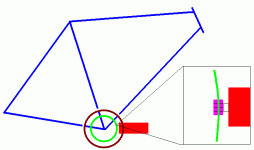
Has anyone tried something like this?

rc motor to freewheel.gif
...the sprocket would have a fine toothed (stiffer) part which would interface with the RC motor and the gear sprocket would be next to it.

This way you get a significant geardown in one step. :)

You could also add extra RC motors to double or triple the power... :twisted:
 
Hi,

safe said:
Has anyone tried something like this?

...the sprocket would have a fine toothed (stiffer) part which would interface with the RC motor and the gear sprocket would be next to it.

This way you get a significant geardown in one step. :)

Great idea but I think the diameter of an RC motor, with a low enough kv to work well, would be too large unless you used a huge gear at the crank.
 
file.php
MitchJi said:
Great idea but I think the diameter of an RC motor, with a low enough kv to work well, would be too large unless you used a huge gear at the crank.
Well I was thinking "very large". If you had an eight inch diameter gear that had 500 fine teeth matched up with an RC motor which had a 10 fine tooth gear then you have a 50:1 geardown. You could make the teeth fine, but wide to add strength. But the core of the sprocket could be aluminum and only the teeth part is made of hardened steel. This would keep the weight down. Ideally you design it so that it mounts directly to a standard bicycle front chainring mounting bolt pattern. (they have several)

So a 6000 rpm motor would produce a crank speed of 120 rpms maximum which does a good job of matching human pedal speeds.

This idea requires someone with the ability to produce extremely strong and precise gears... this is way beyond the ordinary inventor. But the nice thing is that it's a direct bolt on to standard bicycles so the upgrade from standard to ebike would be easier. The RC motor attachment could be achieved with a simple clamp on the frame.

The downside is that there is no "pedal only" mode. (there is motor only and no pedal, but no pedal only and no motor) However, since this requires a front freewheel anyway you could possibly design the freewheeling so as to do both. The big advantage is that this is an easy bolt on to a standard bike. (you could still use at least one of your existing front chainrings)

It would basically be like replacing one chainring with a motor power ring...
 
safe said:
file.php
MitchJi said:
Great idea but I think the diameter of an RC motor, with a low enough kv to work well, would be too large unless you used a huge gear at the crank.
Well I was thinking "very large". If you had an eight inch diameter gear that had 500 fine teeth matched up with an RC motor which had a 10 fine tooth gear then you have a 50:1 geardown. You could make the teeth fine, but wide to add strength. But the core of the sprocket could be aluminum and only the teeth part is made of hardened steel. This would keep the weight down.

Well i see while i have not had time to browse the forum much lately that SAFE is still at it with his marvels of engineering. This one was fun to think about....Safe old friend, there is a reason that people generally use multiple reduction stages for anything much more than 10:1. You would need parts that could not be made or would be so expensive as to be out of the question. Think about what you are saying.

let's be really generous and say you use a 12" (300 mm) diameter 500 tooth gear which is as big as will fit anywhere near the bottom bracket, so its circumference is 3.14 *300 so call it 900. this means the circumference of your smaller gear is 1/50 * 900 or 18 mm so to get its diameter you divide by pi and you get a 6 mm diameter drive gear.

so you now we have a 6 mm diameter gear with 10 teeth. each tooth can be 1/20 of the circumference so call it 1 mm. for the thickness of the teeth, assuming about 50% spacing.

Do you really think a gear the diameter of a pencil with 1 mm teeth is going to drive a one foot diameter gear, also with 1 mm teeth, with enough torque for a bike? Do you think you could keep the dirt out of the teeth? Your idea has been tried, but they use a driven gear twice as big (the 26" wheel) and a rubber friction roller to drive the tire. This way you could put a 1/2" roller on your motor and keep it in contact with the tire like the ZAP motor kit that started it all. You could build the motor into the bottom of a battery box then let it rest on the bike wheel, like they did.

keep at it though, you just might come up with something. and you are good for a laugh on occasion. :D
 
+1

but whenever u try to point how seriously flawed the stuf he comes up with is, u get accused from some other sub-continent of picking on the guy.
so i'm glad to see someone else deliver the cold dose of reality.

Might I request that u also correct in the appropriate thread about mixing chemistries,
http://www.endless-sphere.com/forums/viewtopic.php?f=14&t=1637&p=22955
safe's repeated assertion of how it's okay to run different chemistries tied in series as a normal practice.
I could be wrong, but my understanding from everything I've been taught or read, I think he's crossed the line from laughable to dangerous (to others & not just himself this time), as a little knowledge can be, & would like your view on this.
 
True, true... it did dawn on me that maybe the teeth would be too small and too weak.

However, I'll be testing a motor with a single geardown of 10:1 and that drops a 8000 rpm (overvolted) motor down to 800 rpm. With a single "pre-stage" before you apply it to the big gear it would work.

The main concept here was the idea of a "bolt on" RC motor product and for that (with a "pre-stage") it makes sense.

file.php


The larger "quest" in this was to get away from the "reinvent the wheel" tendency of designers. This approach would stick to the pre-existing chainring bolt patterns.

This would be something what would allow a retrofit of a pre-existing bike.

It's a good idea... maybe needs some "tweeking" but it's cleaner than some of the more clunky ideas out there. :) You have to remember that I've dealt with "transaxles" and multiple geardowns with my old project so I have a lot of practical experience with them. Multistage geardowns need to "be someplace" on the bike and the idea of having that space floating up above the rear wheel (a common place to put it) is not all that appealing. By bringing the "transaxle" back home to the bottom bracket it reduced space. It's a "cleaner design" than floating the gears out on the bike. (it takes less space)

file.php


Think for a second of all the people looking for "front freewheel cranks". The idea is to build a bolt on front freewheel that would also provide the drive for the motor. It's necessary to at some point "connect" the power and the cranks (that is the area that people are having the most trouble) and so with one product you could SOLVE ALL THE PROBLEMS of retrofitting the old bicycle standards to the newer design.

Most people struggle with additional chains... this idea uses the more efficient gear drive. (chains are 95%-98% while gears are usually 98% or above) Plus, chains can make one heck of a racket when run at higher speeds.

29112008438-1.jpg


The idea would be a variation on the "Optibike" bottom bracket, but would not require a special (oversized) bottom bracket so you can use your stock parts. It would be important to include a freewheel for the motor as well as the crank so that they can operate independently. It might be a good idea to design the freewheel for the motor as part of it's geardown. This way the freewheel and the motor geardown are done in one place.

----------------------------

:?: The "Question"

The "Question" this product idea asks is:

"How could you build and sell a bolt on ebike component that could integrate with an RC motor without taking up much additional space?"

The chainring area is a "given" area of space that is used up. By focusing the design so that space that is already "reserved" is used up you do not add additional bulk in other areas. Having multistage geardowns "floating" in space away from the chainring means that you have less space for other things like batteries.

file.php


Recumpence is doing excellent work... I'm not saying that people should divert themselves from what he's doing... but what he's done is something to solve the urgent problems of the "here and now". I'm suggesting an idea that would be more future looking and try to compact the design without forcing a "reinvention of the wheel". (I want something that can be bolted onto any of the millions and millions of bikes already in existence)

We need a simple bolt on, non-space consuming solution... "one day". :)

It's important to remember that the geardown is really just one part of the overall picture too. You still need to deal with the freewheels that apply to the motor, crank and rear wheel. That's three separate freewheels that need to be addressed somehow before you have a completely functional system. (the geardown is just the first step) All this and being 100% backwardly compatible with existing bike parts.

It's not an easy problem... :wink:
 
Another Design

inline geardown.gif
The idea here would be to use a smaller gear on the crank side (the inside circle) and rotate the RC motor so that it's going parallel to the frame tubes. There seem to be a large number of inline geardowns (using planetary gears) that exist so you could get a significant geardown first and then interface with the crank gear at a right angle. The smaller diameter crank side gear could be built stronger and lighter and since you use a planetary geardown you have less to do at the crank.

Having the motor running parallel to the frame is a big step forward because it saves space. The Optibike does something like this, but their bottom bracket is a completely exotic size and shape so normal bikes can't use it.

The things you would need are:

RC Motor
Planetary (Inline) Geardown
Freewheel for the Motor
Freewheel for the Cranks (front freewheel style)
A custom gear on the crank that can accept a gear from a 90 degree angle. (there are various gear "cuts" that might be looked at)

---------------------------------

This should satisfy all the desired criteria:

Does not use up additional space
Bolts on directy to existing bike standards
Allows freewheeling for the motor and the crank
Very high efficiency
No chains, so very little noise
 
Status
Not open for further replies.
Back
Top