major said:
BigOutrunner said:
Did anyone notice in the Honda prototype motor drawing that there are only two copper rings (not 'coils' in a real sense) a U phase and a W phase copper ring, but no V phase copper ring?
Can anyone take a stab at how the V phase 3 dimensional stator segment will be 'powered up' (if at all) without that missing third V phase 'coil'/copper ring?
I noticed that also. I guess maybe they excite the 2 coils as 2 phase 120 degrees apart in the electrical timing. So U and W phases are excited and V phase is a consequence. Similar maybe to DC machines which use a consequence pole (like a 2 pole motor with only one field coil). I've never seen it done with armatures before, so just guessing here. But using the fact that balanced 3 phase has U + W + V = 0, you can derive V from the sum of - (U + W). So can the sum of the U and W mmf's produce the flux in the V stator ring? I think so.
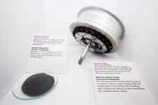
Honda is admitting that the max efficiency they are deriving from the prototype motor is only 71%.
I'm not surprised, since the flux is partially being wasted in 1 extra direction - since it is 3D.
So the flux isn't just moving towards the magnets below the segmented stator in the drawing - it is also flowing sideways, supposedly.
I'm not sure if exciting the copper '120 degrees apart' is possible since these are copper rings and not the usual windings around each teeth.
Which should make the back emf sinusoidal - but I'm guessing here.
Since both U and W phase copper rings are in contact with the V phase stator (which is 3D), the V phase stator is always half active if either copper ring is on.
Thus you are right, if both U and W copper rings the V phase stator would then be fully active.
But then, wouldn't all of the stator phases be active at the same time as well?
Perhaps the sneakier way that the V phase stator is activated is by exciting half of each of the copper rings that are facing or directly touching the V phase stator instead? So the U copper ring is actually half U and half V, powered at the same time, and same goes for the W copper ring.
If you look at the drawing, only 75% of the U phase stator tooth is in direct contact with the U phase 'coil'. The copper isn't wound completely around the tooth.
Because the tooth isn't wrapped 100% like a coil, 25% of the potential to max flux is lost.
Then add say 4% of flux lost to its 3 dimensional nature, so the 71% efficiency Honda is seeing is just about right.
All of this is just wild guess of course.
Our resident motor guru friends would have a better picture, for sure.
")
As Miles said, as a direct replacement for laminations in motors we normally work on, using 3D somaloy core is very inefficient.
But is there any practical, basic configuration where 3D somaloy would be useful, or better than laminations in electric motors? Even a single simple example may broaden our understanding of this new 3D motor technology.
Honda's prototype does not inspire confidence that this 3D thing is actually better than standard laminations.
Shall we label 3D just marketing hype and call it a day?
Thanks All!