ElNormo123
1 µW
- Joined
- Nov 17, 2021
- Messages
- 3
Hi all
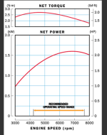
I am trying to make a brake dynamometer for a small 50cc engine (torque and power curves attached). The dyno must be capable of holding the torque of the engine at all speeds. I was thinking of using the following BLDC motor http://shop.dualsky.com/ga6000s-single-shaft-edition-giant-airplane-series-for-e-conversion-of-gasoline-airplane_p0253.html
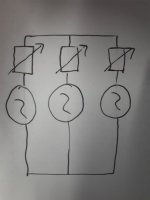
From what I can tell it can get up to the speeds required for the engine and provide a suitable torque. I am planning on electrically braking the motor by varying the resistance in the coils of all 3 phases as shown in the attached picture. To do this I will put some form of variable resistor in each wire coming from the motor and solder them all together. I am not very confident with motors so Im not sure if this will work. My theory is that as turning the BLDC with the engine will generate AC current, I should be able to regulate the resistance in each coil to regulate the current and hence braking torque.
I have a few questions about this.
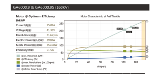
1. When the engine is turning the motor will it generate sufficient current to create the necessary back torque? All the stats on the motors website give torque ratings with 48V across the motor, I assume I will not have 48V when im generating. My understanding of it is that I could use the RPM/V specification to calculate the volts is this true?
2. If the above is true, I have attached a picture of calculations using the max throttle specifications from the companys website (also attached as a screenshot), If these calcualtions are correct I should have more than twice the torque needed to hold the engine. I did the same calcualtions at various speeds and this remains true, I just want to check if the calcualtions would actually represent the true torque or at least close to it.
3. Last question is how to actually control the resistance. I have used PWM controlled Mosfets before with DC but as this will output an AC current I assume I cant still do this, does anyone know of a way to regulate the current affordably? If my calcualtions in Q2 are true I might be making a maximum current of 130A but as the resistors will only be in 1 coil each I assume I can have a resistor with a lower amp rating than this.
Any help would be greatly appreciated
Thanks
Andrew


