12p3phPMDC
1 kW
- Joined
- Mar 16, 2009
- Messages
- 462
Matt,
I was studying my drive design and it occurred to me that I needed
to do a two stage drive. I want a couple of those freewheel adaptors you had made up
for a fixed drive. Are they left handed threads?
I think that this cog in a 13 tooth will work for me. What do you think, are the threads the same?
This what they say about it at harris cyclery.:
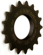
Beautifully machined E.A.I. sprockets. Made in U.S.A.
Fully threaded for strength. Fits all track hubs, also fits most thread-on freewheel type hubs.
Fits all track hubs, also fits most thread-on freewheel type hubs.
Narrow 3/32" width works with all kinds of chain, narrow (derailer type) chain preferred.
Available in 13-22 tooth sizes,
3/32" and 1/8" widths.
(is direct linking of pics not allowed?)
I was studying my drive design and it occurred to me that I needed
to do a two stage drive. I want a couple of those freewheel adaptors you had made up
for a fixed drive. Are they left handed threads?
I think that this cog in a 13 tooth will work for me. What do you think, are the threads the same?
This what they say about it at harris cyclery.:
Beautifully machined E.A.I. sprockets. Made in U.S.A.
Fully threaded for strength. Fits all track hubs, also fits most thread-on freewheel type hubs.
Fits all track hubs, also fits most thread-on freewheel type hubs.
Narrow 3/32" width works with all kinds of chain, narrow (derailer type) chain preferred.
Available in 13-22 tooth sizes,
3/32" and 1/8" widths.
(is direct linking of pics not allowed?)

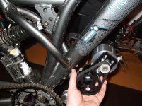
 Secondly, I don't want to jump to conclusions, but you may want to at least considder doubleing up on the zip-tie mounts :lol: