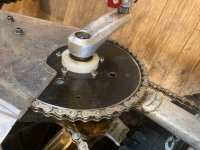
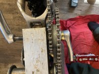
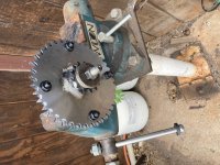
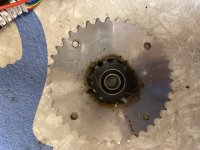
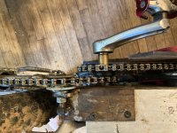
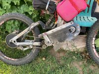
A QS 2000 motor mount from Cyclone 3k plates etc

My budget is limited, I assume I Cannot go wrong with QSMOTOR price-benefit-performance-quality wise.

One might be able to overheat a QS motor but I guess that it's not an easy task.

In addition, Where I live, a dollar is x4 of the local currency so for me cyclone Was just too expensive. My dream was the lightning rods, just a dream...

I can tell you that the qs1kw is small but heavy and compact.

Tonight I'll put that frame together and check if it fits between the pedals without any issues

Did you check the link?
What do you you think?

Sent from my POCO F2 Pro using Tapatalk

 
No, I have not checked the link as I prefer eBay to Alibaba but Alibaba has always come through for me on big purchases.

With Cyclone you get a kit without instructions. With QS Motors you likely get a better motor and better controller for less $$. QS motors have IPM construction and Cyclones do not employ embedded magnets.

As for LR kits, QS motors have been thoroughly used and proven on all the performance e-motorcycles, scooters, karts and cars. For LR's motor you can listen to his chatter -- very little record -- a motor out of the blue?

LR's delivery punctualness? I some years ago ordered his SMBK kit. 4 to 6 weeks professed delivery time. I got the kit 6 months after payment. In the meantime I had ordered a Cyclone 3 k kit. The Cyclone bike was up and running for 4 months before getting a chance to compare it to the LR SMBK -- I would take Cyclone any day.

The biggest letdown of the LR design was the Gates belt. It tore on the first hill climb which was on the first ride. LR had no belts on hand. I found 3 more belts on eBay. They lasted about a week failing on hill climbs with little headwalls. Did his setup get any field testing? The kits were touted for Mtn Bike use.

Now he is grandstanding IPM motors against Cyclone. Truth is any of these magnetic motors work best with the least space between the magnets and the field -- until they heat. Thing is LR is not one to post quantative comparisons for his products. No dimensions when he shows size comparisons. For his motor frame products You pay for a lot of machining when a simpler designs are out there with far less bolts and milled pieces. Changing out the Hall transistors on the LR Sm required a sizable amount of frame removal just to get to them.

Assuming you have the skills and patience to do this QS motor installation, you most likely will have a better product than you would get from LR for less $$$ and more satisfaction.

And I know "...LR is not going to be around..." as pleaded in the eponymous thread. But I note another saying, "Those that forget History are condemned to repete it."
 
Very wise words.

That's what I have in mind. QSMOTOR will be better on the long run.

The link was for aliexpress and was just for the freewheel crank. This is the only thing that's taking my sleep at night but I found a solution.

https://www.sjscycles.co.uk/cranks/shun-alloy-104-pcd-4arm-freewheeling-cranks-170-mm-silver/?geoc=PL&utm_source=pocket_mylist

The link above It's freewheel crankset with 104 bcd adapter.
Looks like plug and play as much as possible to make my life easier. I did the math, sourcing everything piece by piece would be much more expensive plus would have a huge risk of things don't fit.

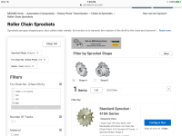
I'm ordering a few sprockets with 17mm hole with different sizesn and patterns. They are super cheap here and I believe one of them will fit and make easier to adapt a bicycle chain on the motor shaft. I'm doing this as a plan B if my grinding on the 428 sprocket fails... Those sprockets are for 25h chain which may fit on the motor for which I believe is strong enough for my application.

When I beginning fitting things together I'll open my own thread

Sent from my POCO F2 Pro using Tapatalk

 
brazilianboy,

Re: grinding the cog sides

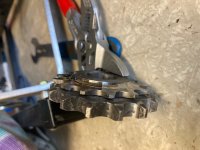
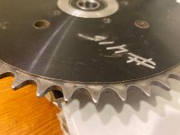
-- grinding the cog sides minimally so the chain rollers sit in the troughs and the chain's side plates press on the cog sides snugly will likely give you a little more cog life. But more cog side removal will result in far less generation of chain-cog contact noise while running. I grind a thinner profile to make for a less noisy power-on ride.

Loose is pleasant.
 
brazilianboy,

There is a way out of doing the grinding -------------

Bolt or weld the motor-chain cog you want to the included cog. The included motor cog may be somewhat hard to drill as the steel cog is a version of some hardened high carbon steel. And for welding this difficult job has to be done slowly and carefully.
 
Was thinking about start with 415 cog and here also I can find a 25h cog with 17mm hole.
25h cogs and chains would work for me?

Sent from my POCO F2 Pro using Tapatalk

 
25H chain? It is used on those rental scooters (200 watts)? strewn all over town. It may work, but it seems that 7k input geared low may put 25H chain near/BEYOND its upper working limit. I once bought some 25H sprockets on a close out sale from Staton Inc -- cheap. They still sit -- waiting for a good application.

Wouldn't a build be easy if we could use shoe lace for chain?
 
Haha yes. Would be amazing.

FIY QSMOTOR 1kW fit perfectly between the pedals of a fat bike with 120mm.

You may have issues depending on the crank arm you use because the clearance is really small. About 10 mm only

Sent from my POCO F2 Pro using Tapatalk

 
For square drive shafts one can find an assortment of different crank bowings from an assortment of old bikes. The square drive cranks do not have a standard offset from the axle mount hole to the pedal threads.

Also you can grind some material off the crank arms and maybe safely on the motor/frame where the cranks touch the motor/frame contact zone.
 
Die Grinding Motor Sprockets

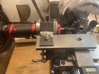
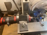
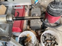
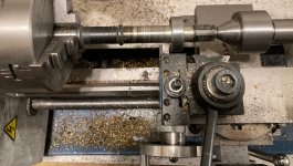
With a traditional turning setup on a lathe you get one carbide tip tool edge cutting on the very hard steel of these motor cogs per pass. Lathe attachment parts stores sell electric grinders that fit on the cross feed or tail stock. These grinders usually are set up to spin grinding wheels that can remove very hard steels -- quite accurately.

With a die grinder set up on a lathe you can spin the die grinder with a 12 edge carbide deburring tool at 20,000 rpm and spin the lathe at 1500 - 2000 rpm without much oiling. Material removal is somewhat faster than a single edge carbide cutting tool.

IMG_1397.jpg

IMG_1400.jpg

The QS motor chain sprockets have 3 degrees of (slightly rounded) taper which can be set with the crossfeed protractor or by angling the bridge plate 3 degrees.

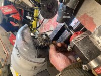
The swarf from die grinder milling needs immediate containment, not that it gets air born like grinder produced swarf, but when left to just fall some of these millions of whisker fibers eventually end up in your finger skin. They are so small that tweezers fail to easily grab them for removal. A sharp apex pointed X-acto blade can get 'em. Most of them are far less annoying than a cactus spine in your finger.

there are 3 things to do mitigate the fiber infestation:

1. Have a vacuum hose mounted & operating quite close to the employed part of the deburring tool used on the die grinder.

2. Spray oil on the nearby surfaces. I use KN air filter oil. The oiled fibers stay put and for some reason do not get in your finger skin much when oiled. Also the fibers readily clump together when oiled.

3. Wear some snug fitting gloves that have the impenetrable rubber on the palm side and finger bottoms. Some machinist say, "never wear gloves around lathe." I say you are just turning the end feed wheel.
 
Thanks for the tips. Last weekend I ordered a lot of parts and tools to start with the build.

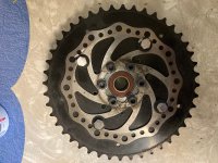
I ordered a kit with motor sprocket 13T and mid-drive sprocket 44t plus chain. All for 415h chain, I will try make it happen. Pedal drive sprocket will also be 44T

The mid-drive sprocket is not 104bcd but I'll just make the holes obviously.

For rear drivetrain I got sram 12 speed cassette with sram gear shift lever and gear selector too.
Peharps overkill but I bought everything used so it came out cheaper than a basic new cassette drivetrain kit. For brakes I got shimano MT200 hydraulic and 203mm rotor front and rear.

My next step will be design and build the motor mounting bracket. But that's a problem for future me

Sent from my POCO F2 Pro using Tapatalk

 
brazilianboy,

The #415 chain is bigger than you need as #410 chain has sufficed on both Cyclone 6k and the QS 2000.

Whew.... I am glad to hear you got these parts cheap -- the 12 speed etc.
 
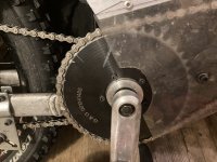
The UHMW(PE) Billet Hub Resurrected

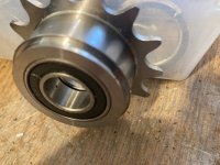
The plastic material for this hub is about $3 and this material makes for the lightest equivalent DFBBH so far. Turning/boring plastic requires very sharp HSS lathe bits, more relief angle and high speed to get clean cuts. But this plastic melts at a low temp. Occasionally you have to stop work and let the lathe bits and plastic cool. Even with this waiting time hub production with UHMW plastic my be the shortest.

The unfinished hub was cleaned up and the bearing insert holes deepened. The resulting bearing holes then were a bit bigger than needed for a tight bearing fit so brass shim stock was wrapped around the outside of the bearing to make for a tight fit.

IMG_1401.jpg

SicBikeParts jack shaft bearings were used after removing the depth stop ring that comes on the outside of the bearing.

The hub is now mounted on the QS2000 ebike for testing and use. It is quiet running.
 
Thanks for the photos. I really appreciate it.

The difference is massive. Luckily I can send it back if 415 kit does not fit on my plans.

But can I use a 415h 44t sprocket with 410 chain?

For now I live in a village in the middle of nowhere in Poland, find someone with a lathe or other specialised machinery is really hard but I will have to if comes to the point I can't do it myself. Your directions really really help! Thank you

Sent from my POCO F2 Pro using Tapatalk

 
#410 chain is too narrow to fit over the width of the #415 sprocket. But you can easily grind down the side of 415 sprocket enough so it can accommodate a #410 chain. Compared to motor cogs most large sprockets are made from much softer steel.

Staton's line of #410 and #415 sprockets are made by turning down #40 sprockets on one side of teeth. They work quite well.

IMG_1410.jpg

This material removal from the sides of the big sprocket does not require lathe like precision. Make sure you get both complete chain lay down in the slots and a little side play between the teeth at the narrower plate sets on the chain.
 
Shim Stock Creeps out of UHMW(PE) Billet Hub

On a second ride (a few miles of snow and hills) employing the UHMW hub the hub began making regular noises. Examination revealed the shim stock had worked its way out of the sides of the bearing. The hub assembly was thrust washered snugly to not allow lateral motion on the hub BB shaft. The missing shim stock permitted the sprockets to wobble a little bit. I was able to ride to the trail head without either chain coming off.

IMG_1235.JPG

Apparently the plastic hub material is quite slippery and cannot retain brass wraps on bearings. Most glues (Loctite shaft lock etc) do not stick to PolyEth. The shim fit was tight.

I suspect, if the hub had had a quite tight fit to the bearing without shim stock, the bearings would still be in place and the hub working fine.

I am now testing the aluminum billet hub.

IMG_1236.JPG
 
Installing Motor Sprocket Tightening Bolt on End of Motor Shaft

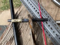
The task of drilling and taping on the QS motor shafts is quite difficult due to the very high degree of case hardening on the motor shaft. The wide splined motor shaft gets bigger towards the motor side after parallel matchineing for a distance wider than a motor sprocket. A motor sprocket forced onto the wider splines gets very tight & secure which is desired. Forcing a motor sprocket onto the wider splines is not easily done with the IOM QS lockring nor by an added external milled snap ring that just fits very snug.
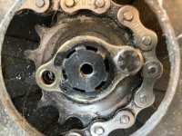
IMG_1497.jpg

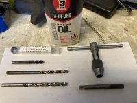
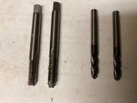
To tap threads into highly hardened steel necessitates carbide drills and carbide taps -- plus very careful work to keep from breaking the solid carbide tools. A carbide drill mill and a carbide tap from MaMater-Carr costs $123. I could get these two tool on eBay for $39 -- perhaps inferior but maybe they could do the job?

An earlier attempt of the shaft conversion to an end bolt system was attempted by drilling the shaft end with an 1/8" round nosed carbide deburring tool. A deburring tool can follow a hole adequately but they often do drill new holes as out-of-round holes and bore a non straight hole. I quit on this drill/deburring task and decided on a drill bit first tactic. A 90 degree pointed carbide drill mill is likely to drill a truer hole than a solid carbide twist drill. Hence a 3/16" drill mill was used to initiate the boring.

The size of the holding bolt desired was a 5mm Allen head class 12.9 size M6 x 1.0 and length of 20mm. The tap drill size is 5mm for that bolt. 3/16" drill mills are readily available in the US as most mills are still English size. After carbide drill-milling the 3/16" hole a 5mm cobalt twist drill bit was used to ream the hole to the 0.2047" which is the tap hole diameter. The case hardening maybe 1/4" thick so a cobalt twist drill could do the remaining & drilling after the carbide drill mill penetrated into the non-heat treated steel. The tap wrench was seldom turned more than 60 degrees -- there were 3 sets of cutters on carbide tap. After each backing out of the hole a clean out was done with oiled cotton swabs.
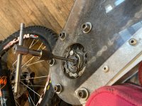
IMG_1494.jpg

The QS2000 shaft tapping went without difficulty probably because the shaft end had a bigger tapered entry hole than necessary for the tap to abruptly start cutting threads. The QS 3000 had no taper at the top of the hole and soon the carbide tap tip broke an edge off of one cutter flue -- the tap was now worthless for any hard metal cutting. To get a larger tapered hole at the start of the motor shaft a 1/4" round nosed carbide deburring tool was used to mill into about 1/8" of the end of the motor shaft.
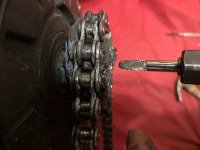
IMG_1502.jpg

On the shaft 2 washers with 20+mm diameter were added to give a stack height about 0.030" height above the shaft end. Then a big washer was bolted to the shaft end compressing some of that 0.030" overheight washer stack to wege the motor cog onto the widening splines on the other end.

Both the QS 2000 & the QS3000 now have very snug motor cogs.
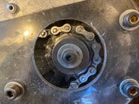
IMG_1498.jpg

IMG_1499.jpg
The 3/16" drill mill bit:

https://www.ebay.com/itm/352325412141

The solid tungsten carbide 6mm tap:

https://www.ebay.com/itm/352325412141

Evidence upon completion of 2 bolt installations:
IMG_1503.jpg

Would the tool tips fair better if the motor had been removed and the work done using a drill press? A hand turned chuck of a drill press gives consistent alignment and still gives a sense of feel when binding occurs.
 
Very determined as usual! I’d definitely break a tap or drill bit and have the sharp end stuck in the motor shaft. I’d get the belt drive versions of the motors and go from there for a bolt on solution.
 
Hi Skaiwerd,

A belt drive sounds wonderful -- quietness like an idling car motor?

Circa 2016: I finally got my long awaited Lightening Rods Small Block with an OEM Gates Belt- maybe a motor of 2500 watts? I put the kit on a brand new Specialized Fat Tire Bike -- the press fit BB was a problem -- soon overcome.

As for History, those that forget the past are condemned to repeat it. The LRSB Gates Belt tore the belt on the first hill climb -- 300 feet from the car. My then recently built Cyclone 3K with chain drive had done this hill several times. I think maybe a bad belt? I buy 3 more belts. They lasted maybe a week. I considered changing the drive to chain. You can put Lipstick on a Pig. But .......I very soon sold the Hog -- thinking creates better rationale for action?

One could argue that the belt was too narrow for the [impact load] load? Okay perhaps the belt was 10 mm wide so we get a 20mm wide pulleys etc and suppose it works after testing -- something that LR likely never did?

Upscaleing to QS3000 motor torques we get a belt 6x wider -- about 120mm -- and find the new pulleys stick out more than desired. After some worthy hillclimbing we discover the metal pulley's teeth chew away the belt teeth and soon the belt has flat zones of no teeth on the inside.

I have a metal turning lathe that is Gates belt driven. Swarf snags occur while turning -- the rubber teeth are then torn from the inside of the belt. The belts never break but become about toothless if used until they cannot turn the stock [at a non-steady speed].

A drive belt may work for the highway but shock loading [from rotating inertia against a snag] tears teeth off the belts. Chains as opposed to belts remain more intact when encountering shock loading situations -- can you imagine a toothless chain? Perhaps you could use the belt like a safety fuse against too much shock torque? What-the-Hell an occasional bike push builds character? My chains get me home without pushing -- though I have employed pieces of chain that I carry for when a chain breaks. You could carry several spare belts? And push the bike up shock loading routes -- forget it "that trail is a worthless...POS".

Show me a motorized belt driven dirtbike

Earlier: after seeing the QS motor with the bolt tightened belt pulley I envisioned a way to utilize those good features employing a chain drive cog mounted on the belt drive pulley-- but maybe that feature would be wider than what I now have?
 
I should have elaborated. Get the belt drive motor for the slotted straight shaft of 17mm. Use your choice of sprocket and chain.
 
UHMW Billet Hub Revisited

In the last 2 hub reports (you can view them up a few posts) of testing a billet hub made of UHMW (PE) plastic it was found that the brass shim stock used to seat an axle bearing in an oversized bore hole worked out of the hub. I have figured out a mechanical way to keep the shim stock wrapped around the bearing even though this plastic is quite slippery. The method has passed field testing.

The machineing of this plastic can go very FAST making the turned hub stock quite WARM. For this plastic a seemingly tight bearing insertion hole bored & tested as tight when the hub stock is warm will usually make for a loose bearing fit when the material cools to room temps. Maybe do the final material removal (to fit) of bearing boring after cooling the material?

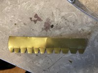
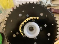
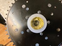
If you get a loose bearing fit, you will need shim stock thicker than one half the amount the bore hole diameter exceeds the bearing diameter. The securement of the shim stock happens by making many brass folds onto the inside of the bearing face and using axle thrust forces to pinch this folded material against the internal annular plastic face of the bore hole. Make shim stock width 1.5 x bearing thickness + annular width of bearing.

IMG_1504.jpg

Bend each trapezoid upward 90 degrees with all trapezoidal tops on the same side.

IMG_1505.jpg

Work this folded brass into the bearing hole with trapezoidal shapes going in first.

IMG_1506.jpg

The extra wall height on the shim sides aids in getting the bearing insertion started. After full insertion the extra height can be cut off or bent over.
 
Building Up the Square Drive Shaft

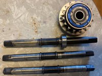
The ID of a square drive bearing is 0.631" and the bearing fits on a case hardened zones of the BB shaft. Employing these bearings elsewhere on the shaft at 0.623" OD requires either brass shim stock or building the outer zone of the shaft to near 0.631" to get a snug bearing fit. Jack shaft bearing fit is at best loosely snug on the non hardened zone.

Getting a snug shim fit under both bearings of the DFBBH is not easily done -- Hence build up the shaft...

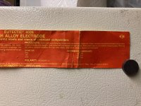
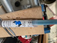
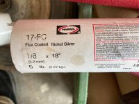
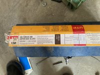
You will need to choose a welding method and the welding rod. I did both arc welding and acetylene.

Some of the rod tried:

IMG_1337.jpg

IMG_1544.jpg

IMG_1546.jpg

IMG_1547.jpg

No picture for generic FC brass rod but overall it works and is by far the easiest to weld and machine.

You will need some method to hold and occasionally turn the BB shaft while welding/brazing as when the shaft gets too hot the rod material will run to the bottom leaving the top side too thin.

IMG_1542.jpg

IMG_1538.jpg

After the welding build up has cooled the BB shaft other end is tightened into the lathe chuck and the built up end was held in place with a tail stock bearing.

IMG_1548.jpg

IMG_1541.jpg

The goal of this work was to reduce chain speed which is done by using small drive sprockets. Small drive sprockets <24T do not fit on the hubs made from billets that are using the F5 bolting pattern. Earlier versions of these bike part made hubs (as low as 16T drivers) needed bearing shimming -- tedious.

The QS 2000 build is running an 18T WI driver on the DSBBH and the QS3000 has a welded (to stop freewheeling and falling apart)Dicta 16T #415 freewheel sprocket on the DSBBH. Both these ebikes' DSBBH are made from bike parts and are mounted on built-up square drive shafts. So far no problems and less chain noise as it travels slower than when the DS billet hubs were running 24T sprockets.

Likely welding/brazing/slow cooling on these shafts removed any Martinsitic hardening. The melting point of the brass is more than 100C degrees above the Currie temp to begin cooling for Martensite so I finished one hot shaft with an oil quench. The unquenched shafts are doing fine.
 
BB Hubs Made from Type A Sprockets Combined with Type B Sprockets

Chain sprockets have several shapes. Flat sprockets for bolting or welding to a hub are Type A or Shape A. Sprockets to mount on a shaft and turn the shaft are TypeB or shape B.

IMG_1369.PNG

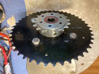
A dual sprocket BB hub was made by bolting a Type A sprocket to a Type B. The Type B hub was bored to fit square drive BB axle bearings. Two square drive axle bearings were implanted into the hole.

IMG_1579.jpg

IMG_1584.jpg

IMG_1581.jpg


Attaching the Type A to the Type B by taping threads into the Type B was time consuming so the next prototype hub was made by welding the Type A to the rim turned Type B sprocket. Welding these sprocket types together will distort a bored bearing hole so bore the bearing holes after the welding is done.

IMG_1615.jpg

Type B sprockets smaller than 13T do not have enough rim material to bore a hole the sizes of the standard square drive bearing.

IMG_1686.jpg

But a 12T Type B sprocket having a 3/4" bore was fit with a 5/8" bushing on the teeth side and a square drive bearing on the side a 23T Type A sprocket was welded to the Type B.

IMG_1684.jpg

Using driver sprockets of 10T and 12T has reduced chain speed -- a little more quieter. The sprockets now in use are 23/10 x 40/12 = 7.666 gear ratio.

IMG_1685.jpg

These lathe assisted sprocket hub creations have some options that are somewhat easier to set up on a lathe than others. Sprockets that have a teeth count divisible by 3 will fit and center readily into the 3-jaw chuck. Even numbered teeth counts can be centered into a 4 jaw chuck with a live center on the tailstock. Using a 13T Type B Sprockets likely will require some faceplate fastening to bore the bearing hole after welding.
 
DingusMcGee said:
Using driver sprockets of 10T and 12T has reduced chain speed -- a little more quieter. The sprockets now in use are 23/10 x 40/12 = 7.666 gear ratio.

Is that not a horrible ratio for a hunting configuration?

Yup. Every 1 turn of the chain a4round the front ( small) the same link on the same tooth..... and rear? Every 10 turns of the chain, the same tooth hits the same link. IF the chain is an even number of links.. ( This is IF and only IF. )

( if the chain has an odd number of links, this ratio is fine.. 12 vchain rotations per same link/tooth on the front, and 40 rotations of the chain around the sprockets creating the same link same tooth situation, so this is much lower and slower wear factor on the teef)

Yes, it is. I do not suppose it matters much, but might, if they are under any significant loading. IN the long term. IF you care. Bout longevity. Noise.. Loss of drivetrain efficiency. Drivetrain power loss. That kind of shit.... parasitic mechanical losses. I know a good rocket bike would chew up both of the cogs on that kind of a ratio... ratio like that... in a day, if not a few hours of racing.

I do want to say this is some incredible work, and ingenuity, in this project.
 
Back
Top