Ampera/Volt inverter with Lebowski brain

arber333 said:
Exactly! CV shaft was rubbing on the edge of CV tripod casing. Whenever the three lips of the casing would come near the shaft on the underside they would rub on it. In time this would have destroyed my shaft. As it is now everything now works and i am trying to tune up the transition like Arlo said. Well i figured i want to have transition to sensorless at as low RPM as possible, because whenever i try to start motor shakes a bit and 1/2s goes by without traction.
But higher in the RPM i am able to burn rubber even at 60km/h! I am sure i could get more power out of it, but my poor battery developped bulges at 400A! So calculating 400A at 355Vdc i pushed some 142kW into the motor. That is not "halfh" bad. 8)
Notice the pun at 1/2 bad? Since my plan is to use both sides of Ampera inverter...

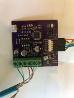
Given how amazing the Lebowski sensorless algorithm is I agree that making the transition to sensorless at the earliest possible erpm is the best strategy. I have also found that when running the resolver-hall converter on the hyundai HSG IPM motor with the Lebowski controller I had to adjust one of the control loop parameters to get really smooth starts but I can't recall which one. I was able to tune out the Hall signal offsets just like you would do if you had actual Hall sensors so the converter is working as expected. I need to do more field testing and a minor update on the pcb layout. I'll take a look at the control loop settings and get back to you.Resolver_Hall.jpeg
 
Please tell me what parameter you did setup for a smooth start.
Right now i have very good pull after 10km/h and insanely good after 30km/h. But before that from standstill there is some shaking like motor couldnt decide to which side it wants to turn to. Lowering the transition further wont do since below 300erpm motor starts to buck a lot.
I got a much smoother start when i lowered the "change direction authority" value as low as possible.
 
arber333 said:
Please tell me what parameter you did setup for a smooth start.
Right now i have very good pull after 10km/h and insanely good after 30km/h. But before that from standstill there is some shaking like motor couldnt decide to which side it wants to turn to. Lowering the transition further wont do since below 300erpm motor starts to buck a lot.
I got a much smoother start when i lowered the "change direction authority" value as low as possible.
It is that below 300 erpm range that you need to get running as smooth as possible to get clean transitions from drive mode 2 to drive mode 3. I have found that for high pole pair count hub motors that the default settings always work exceptionally well but in low pole pair motors like the IPM motors used in the Leaf and also the Hyundai HSG motor that is a 3 pole pair motor you need to make some changes. The single parameter that made the biggest difference to low rpm drive mode 2 operation is lowering the PLL bandwidth in menu L) sub menu e) . At the default 100Hz the HSG rumbles and is rough but at 50Hz it is smooth. Secondly in menu G) sub menu g) increasing that also seems to help. I currently have transition from drv2 --> dr3 set at 400 erpm and dr3 --> dr2 at 200 erpm on the HSG and it works perfectly. I still find I need to tweak the stator resistance figure to get perfect running in sensorless. This is all assuming that your other settings are correct so ymmv.
 
kiwifiat said:
It is that below 300 erpm range that you need to get running as smooth as possible to get clean transitions from drive mode 2 to drive mode 3. I have found that for high pole pair count hub motors that the default settings always work exceptionally well but in low pole pair motors like the IPM motors used in the Leaf and also the Hyundai HSG motor that is a 3 pole pair motor you need to make some changes. The single parameter that made the biggest difference to low rpm drive mode 2 operation is lowering the PLL bandwidth in menu L) sub menu e) . At the default 100Hz the HSG rumbles and is rough but at 50Hz it is smooth. Secondly in menu G) sub menu g) increasing that also seems to help. I currently have transition from drv2 --> dr3 set at 400 erpm and dr3 --> dr2 at 200 erpm on the HSG and it works perfectly. I still find I need to tweak the stator resistance figure to get perfect running in sensorless. This is all assuming that your other settings are correct so ymmv.
Really good.

I noticed that menu "l" sub "e" PLL bandwith causes control loop to behave differently. I actually got little better results by increasing it to 120Hz and i also increased dampening in "l" sub "f" to 0.85! What did you set sub "f" to in your drive?
Also in how large steps did you increase "g" sub "g" to notice results? By 0.01 or more?
I will try your suggestion as soon as i come home...

tnx
 
YA! It is much better.
I used PLL value 50 and tried as low as 35 and i think 50 is better. I kept filtering at 0.88.
Then i increased 2nd order parameter "g" in menu G from 0.3 to 1.8! It immediately felt smoother traction though acceleration was not all that great from 0 to 30.

I guess lab loads are one and car traction is different thing altogether...
Tomorrow i try again and make a different setting in menu G to see variation.
 
arber333 said:
Really good.

I noticed that menu "l" sub "e" PLL bandwith causes control loop to behave differently. I actually got little better results by increasing it to 120Hz and i also increased dampening in "l" sub "f" to 0.85! What did you set sub "f" to in your drive?
Also in how large steps did you increase "g" sub "g" to notice results? By 0.01 or more?
I will try your suggestion as soon as i come home...

tnx

I left l) sub f) at the default. I have had g) sub g) as high as 15 but it is a case by case thing. I would strongly suggest that you switch back to sensorless and turn off any acceleration limiting you have and get the motor running perfectly in no load sensorless mode before switching to sensored mode. That means being able to run the motor smoothly in drive mode 2 at very slow speeds and getting a seamless transition to drive mode 3 and full throttle from zero to max rpm without issues. No load acceleration rates put the control loop parameters under a much brighter spot light than loaded rates. In the early days I use to use the acceleration limiter to mask poor loop parameter tuning but no more.

arber333 said:
YA! It is much better.
I used PLL value 50 and tried as low as 35 and i think 50 is better. I kept filtering at 0.88.
Then i increased 2nd order parameter "g" in menu G from 0.3 to 1.8! It immediately felt smoother traction though acceleration was not all that great from 0 to 30.

I guess lab loads are one and car traction is different thing altogether...
Tomorrow i try again and make a different setting in menu G to see variation.

That is great news. One thing is for sure if your motor runs like crap under no load it won't be any better under load. My experience has been that a motor that functions well under no load is equally good under load. Phase current settings affect torque far more than these settings so don't expect any improvements here to give you better off the line performance. You also need to make sure that the sum of the two polynomials you have entered under the throttle menus is at least equal to one. If they don't you will never get the phase current set under the current menu delivered to the motor. It would much easier to help further if you posted your current config file.
 
I will post my file...
Currently my motor is in a car and i want to keep it there :). It runs really good. But i need to tune up the transistion. Do you think i can do that with one wheel in the air? I think when unloaded motor does not show the same indecision at start. This only happens when i load it.
 
Here are my settings in hex format.

I have changed the g menu value to 5 and i think i get smoother takeoff.
However when i played with throttle curves i got different results from same settings. Strange.

My throttle is 1.3 3 0
My regen is -0.3 0 0

Doesnt that mean it is ok? 1.3 - (-0.3) is essentially 1 yes? But i use 3rd rate curve because the pull is so good after 30km/h!

Here is one run. I think 9s to 100km/h is quite good for now.
https://www.youtube.com/watch?v=OCpP4lDW-xg
 

Attachments

  • Leaf 2020.txt
    2.3 KB · Views: 30
arber333 said:
Here are my settings in hex format.

I have changed the g menu value to 5 and i think i get smoother takeoff.
However when i played with throttle curves i got different results from same settings. Strange.

My throttle is 1.3 3 0
My regen is -0.3 0 0

Doesnt that mean it is ok? 1.3 - (-0.3) is essentially 1 yes? But i use 3rd rate curve because the pull is so good after 30km/h!

Here is one run. I think 9s to 100km/h is quite good for now.
https://www.youtube.com/watch?v=OCpP4lDW-xg

Your throttle looks good, I will take a look at your hex over the coming weekend. Good to hear things are improving with the changes. There is a graphical tool in the throttle menu to make sure everything is sane and it pays to use it just to be sure the settings are correct.

Lifting one wheel off the ground should be sufficient to run the motor in sensorless mode. It may pay to raise the mode 2 --> 3 erpm so you can get the motor run continuously in mode 2.

The start in the YT video looks pretty good but hard to say for sure because of the music in the background. Have you done a top speed run yet? If so what is it?
 
kiwifiat said:
Lifting one wheel off the ground should be sufficient to run the motor in sensorless mode. It may pay to raise the mode 2 --> 3 erpm so you can get the motor run continuously in mode 2.

The start in the YT video looks pretty good but hard to say for sure because of the music in the background. Have you done a top speed run yet? If so what is it?

I will try it with one wheel up...

Yeah it is just a 0 to 100km/h video so i could later calculate acceleration approximately.
I got the car up to 140km/h on the highway. I didnt want to attract attention because i dont have legal highway sticker yet :).
I think it would certainly make 150km/h if not more.
I think it would stop there because i only have 200A reserved for FW. I would need better battery for more. At least 400A capable for 2min.
EDIT: I did go up to 150km/h. Here motor draws 120A and RPM limiter kicks in and cuts the torque. Maybe i could widen this area a bit so control wouldnt be so jerky. But limiter works good.

How is your control loop parameter n) i use 96 but i see original is 48

Also i use "hall assisted sensorless" option. I havent yet changed menu g option c) from 24 to 96 like the manual states is better.
 
OK i think i got the car to takeoff much better now.
What i did was change g) sub g to 12 and there it was running the best.
I also recalibrated hall sensors menu. and lowered some transition values from mode 2 to 3.
In the beginning there is a slight shake or undecision and a little roughness but if apply throttle motor goes forward immediately and when RPM is developed its just smooth.
I noticed however if i go for only sensored mode motor would lurch violently just after first few RPM. If i used "assisted sensorless" option this wouldnt happen.
If i tried to use only sensorless mode motor wouldnt even budge.
 
Another update....
I stil got various shakes in the motor before mode 3.
Now i tried to change various control parameters and without luck i started to shift my thinking from 3rd gain parameter of mode 2 to the whole picture. This is menu g. First i corrected the 2nd gain parameter under option f to 48 and i kept option g at 12.
It seemed there was some small improvement.
Finally i changed f to 96 and experimented with g at 8. This gave best results. So gain has to be adjusted as a whole. I also changed transition from 2-3 to 88erpm. This shifts to mode 23 almost immediately and causes the least shaking.
Now when i drive slowly in a parking lot i can smoothly move the car for parking!
 
arber333 said:
Another update....
I stil got various shakes in the motor before mode 3.
Now i tried to change various control parameters and without luck i started to shift my thinking from 3rd gain parameter of mode 2 to the whole picture. This is menu g. First i corrected the 2nd gain parameter under option f to 48 and i kept option g at 12.
It seemed there was some small improvement.
Finally i changed f to 96 and experimented with g at 8. This gave best results. So gain has to be adjusted as a whole. I also changed transition from 2-3 to 88erpm. This shifts to mode 23 almost immediately and causes the least shaking.
Now when i drive slowly in a parking lot i can smoothly move the car for parking!

That is good news. I took a look at your config file and noticed you had 11.35 degrees error with standard deviation of over 23 degrees in your Hall signals. Good that you have re-tuned them, you should be able to get the error down to 1 degree or so. It is not a bad idea when tuning the Hall error that you do so only at low rpm as that is the only range that matters. I usually set the rpm limiter low and blip the throttle a hundred times or so to collect data for Hall error tuning and then remove the limiter once I have error down to a degree or so.

Since you want to switch to sensorless drive mode 3 as soon as possible I can't understand why you still have the transition in n) sub h) set at 35,000 cycles. IIRC Lebowski has recommended that you drop that to the default and that you don't use Hall assisted sensorless. I'm sure it is only masking a configuration error.

You are right about the importance of menu G) sub menus e,f,and g appear to be the most critical in tuning the transition from drive mode 2 --> 3 . Dropping G) sub e) can also help.
 
kiwifiat said:
That is good news. I took a look at your config file and noticed you had 11.35 degrees error with standard deviation of over 23 degrees in your Hall signals. Good that you have re-tuned them, you should be able to get the error down to 1 degree or so. It is not a bad idea when tuning the Hall error that you do so only at low rpm as that is the only range that matters. I usually set the rpm limiter low and blip the throttle a hundred times or so to collect data for Hall error tuning and then remove the limiter once I have error down to a degree or so.

Since you want to switch to sensorless drive mode 3 as soon as possible I can't understand why you still have the transition in n) sub h) set at 35,000 cycles. IIRC Lebowski has recommended that you drop that to the default and that you don't use Hall assisted sensorless. I'm sure it is only masking a configuration error.

You are right about the importance of menu G) sub menus e,f,and g appear to be the most critical in tuning the transition from drive mode 2 --> 3 . Dropping G) sub e) can also help.

Hm... i totaly forgot that N sub h parameter. I had it set because if set to 1000 it caused shakes in drive 23. I will try again.
Bas himself told me to set erpm transistion from 2 - 3 and 3 - 2 at least 1500erpm apart. I have been trying to shorten that gap but it seems he was correct.
I see really good results with Hall assisted sensorless option if i would turn it off i would get all sorts of vibrations in drive 2 as well as conkouts in drive 3 at speed which is what frightens me the most.
I will try to tune out Hall sensors like you propose. I get a feeling the value has drifted a bit from last time i observed. I am using RLS RMF44 sensor chip and magnet on the end of shaft. I zeroed out the sensor when i built it in but now i dont have enough access to attempt to zero out the chip again.

When you set RPM limiter you mean actual limiter when driving or the one to test sensor response in menu L?
 
arber333 said:
I will try to tune out Hall sensors like you propose. I get a feeling the value has drifted a bit from last time i observed. I am using RLS RMF44 sensor chip and magnet on the end of shaft. I zeroed out the sensor when i built it in but now i dont have enough access to attempt to zero out the chip again.

When you set RPM limiter you mean actual limiter when driving or the one to test sensor response in menu L?

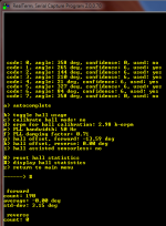
Here is a screen shot of the Hall stats after tuning using my Resolver to Hall converter on the Nissan Leaf motor. I have 0 degrees average error and SD of 3.15 degrees. I am usually lucky to get that close with an ebike hub motor fitted with Hall sensors.

Hall Tuning.PNG

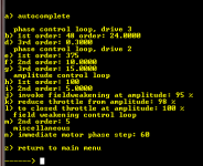
This is my menu G settings:
menu_G.PNG

If I set G) sub N) higher than 64 I can hear strange harmonics in the motor. I have the transition cycles from drive 2 --> drive 3 set at 500 in N) sub h).

When the G) sub e) f) and g) are wrong the motor runs rough in drive 2 and the transition is also rough. If you can get the Hall errors and standard deviation down I'm sure it will help with a smooth transition into drive 3.
 
Really appreciate this thanks!

Yesterday i was driving and calibrating hall sensors. First i tried to calibrate them with my wheel up. I got very different results.
One time i managed to get a fast response from the motor on start. I got 3 sensors at 7 confidence and 3 at 6. Otherwise they are all 6. But when i started to tune them up everything got sluggish again.

Also i see you have entered -13.6deg correction but you managed to get sensors to 0error? Can you confirm that i need to set the correction in option g) and recalibrate sensors untill i get 0 average error? My dev is usually at 20deg :(.

Will try like you say...
 
arber333 said:
Also i see you have entered -13.6deg correction but you managed to get sensors to 0error? Can you confirm that i need to set the correction in option g) and recalibrate sensors untill i get 0 average error? My dev is usually at 20deg :(.

Will try like you say...

Yes , if you look at the Nissan Leaf resolver it has no adjustment facility unlike the Sonata HSG or the Toyota hybrid motors. Allegedly the Leaf motor has the resolver offset encoded into the serial number. I could tune the error out in the resolver to Hall firmware but it would be pointless since the Lebowski controller cleverly has this ability. Interestingly the Hyundai HSG motor that does have adjustment only has 2 degrees of error that needs to be corrected. And that is electrical degrees, so the mechanical error for the 3 pole pair motor is only 0.67 degrees. I have a low pass filter on the sin and cosine feedback into the CPU which probably accounts for most of the error.

What you need to do under menu L) is zero the Hall statistics. Jack up one drive wheel and collect 100 samples. Save the data and enter the menu and see what the current error is under menu L). Enter the offset correction in L) and reset the Hall statistics. Take another 100 or so samples and repeat the process.

You should be able to get consistent results, if you can't you will need to track down the cause. You may want to add some extra supply bypassing capacitance to the RLS encoder. IIRC Arlin experienced a few issues with his RLS encoder. Coleasterling has fitted an RLS encoder to the back of a HSG motor, it will be interesting to see what results he gets as a point of comparison.
 
Hm... interesting.
Last weekend i went on and started to calibrate like you said. Over 100 samples patiently collected with small steps of +/-1,5deg. Curiously the final value kept moving away from me in steps of 1 or 2deg. Then finally i lost my patience and commanded a 10deg step. I collected more samples and i finally got the -2deg value. Which meant i crossed actual 0deg. I corrected that to within 1 deg of variation and 0deg actual! Values were +29deg for forward and -28deg for reverse. And i didnt calibrate reverse fully.
I also increased max phase current to 550Arms and corrected your menu g settings.
Now i got good and steady acceleration from stop. But i still have to calibrate in reverse. I am very pleased with the car now. It seems i shed one second from 0 to 100km/h which is no small feat for 1,6T weight and 70kW limited car.
I will need to wait for better battery to test acceleration further (and using both inverter sides).
 
arber333 said:
Hm... interesting.
Last weekend i went on and started to calibrate like you said. Over 100 samples patiently collected with small steps of +/-1,5deg. Curiously the final value kept moving away from me in steps of 1 or 2deg. Then finally i lost my patience and commanded a 10deg step. I collected more samples and i finally got the -2deg value. Which meant i crossed actual 0deg. I corrected that to within 1 deg of variation and 0deg actual! Values were +29deg for forward and -28deg for reverse. And i didnt calibrate reverse fully.
I also increased max phase current to 550Arms and corrected your menu g settings.
Now i got good and steady acceleration from stop. But i still have to calibrate in reverse. I am very pleased with the car now. It seems i shed one second from 0 to 100km/h which is no small feat for 1,6T weight and 70kW limited car.
I will need to wait for better battery to test acceleration further (and using both inverter sides).

That is good news. Were you able to disable "Hall assisted sensorless" ? I noticed that you have the Leaf motor stator inductance set really low. Try setting it back to 230mH and stator resistance to say 100mOhms and disable Hall assisted sensorless and take it for a test drive. I know Arlin lowered stator inductance down to get maximum horse power but I think you will get better behaviour from the motor if you set it closer to its actual value.

In other news I cleaned up the resolver exciter drive signal with a low pass filter on the output and I am now able to leave Menu G) sub e) and f) at their default values and g) to 5. I'll post a video soon.
 
kiwifiat said:
Try setting it back to 230mH and stator resistance to say 100mOhms and disable Hall assisted sensorless and take it for a test drive. I know Arlin lowered stator inductance down to get maximum horse power but I think you will get better behaviour from the motor if you set it closer to its actual value.

Hi

I tried to use 230mH and 100mOhm. Car started fairly well, but a second into acceleration controller reduced power. I couldnt get it to pull continuously through. This was with sensors assist off.
But then if i reduced inductance to some 150mH i could get a good start, but again controller would reduce power after a second or so.
Then i dropped resistance to 48mOhm and start was really good, but above 30km/h i would get a sudden jolt in motor! That was without hall assisted sensorless.
If i turn that option ON the car does shake a little on start but only 0.1s then it can pull off and drive in sensorless.

I have never had a conk out at speed or in FW! So for me Hall assisted sensorless works well.
 
arber333 said:
Hi

I tried to use 230mH and 100mOhm. Car started fairly well, but a second into acceleration controller reduced power. I couldnt get it to pull continuously through. This was with sensors assist off.
But then if i reduced inductance to some 150mH i could get a good start, but again controller would reduce power after a second or so.
Then i dropped resistance to 48mOhm and start was really good, but above 30km/h i would get a sudden jolt in motor! That was without hall assisted sensorless.
If i turn that option ON the car does shake a little on start but only 0.1s then it can pull off and drive in sensorless.

I have never had a conk out at speed or in FW! So for me Hall assisted sensorless works well.

That is really strange, that feature is intended for situations where there is sudden acceleration like when a off road dirt bike looses traction going over a jump or similar. It should not be necessary to use that feature to get you Leaf motor to run smoothly which I expect is the reason Lebowki did not recommend it for your application. I think maybe it is masking some other issue, do you still have your transition from drive 2 --> drive 3 in menu N) sub h) set at 35,000 cycles? I have never needed to touch the FOC inductance value to get a motor running well. I have run axial flux, IPM and SPM motors with pole pair counts ranging from 3 through to 36 and only ever needed to increase the stator resistance value.
 
kiwifiat said:
That is really strange, that feature is intended for situations where there is sudden acceleration like when a off road dirt bike looses traction going over a jump or similar. It should not be necessary to use that feature to get you Leaf motor to run smoothly which I expect is the reason Lebowki did not recommend it for your application. I think maybe it is masking some other issue, do you still have your transition from drive 2 --> drive 3 in menu N) sub h) set at 35,000 cycles? I have never needed to touch the FOC inductance value to get a motor running well. I have run axial flux, IPM and SPM motors with pole pair counts ranging from 3 through to 36 and only ever needed to increase the stator resistance value.

Yes well...
My motor ran perfectly well on desk without load. But when it is coupled with 1600kg vehicle and 550Arms current i first couldnt get it to run on autoset parameters. I needed to increase stator resistance up to 3x of what brain measured. The best setting for good enough start was 48mohm.
But good enough start i mean some shaking and motor banging on start with smooth transition to sensorless later.

I just broke the 3rd motor mount :(. Of course it was my fault. I made it too flimsy and was banging it with full power at start!
I think i will revisit my RLS sensor cable and its shield grounding points.
Then i think of adapting better sensor filtering. I am now using 1nF caps directly on the chip inputs with no pullup resistors since my RLS board has push-pull output. You think i should also use like 1K inline resistors? Or should i remove those caps?
 
Finally new mount is in. It was done propperly like i should have done before :roll:
https://leafdriveblog.wordpress.com/2020/11/10/busted-rear-mount/

Now i tried again with 220uH and 100mOhm setting and i found out that motor can start rather smoothly although minimum power. Then at some 45km/h (maybe 1500erpm) motor gives a huge kick and transitions to sensorless whwere it runs smoothly.

Why the kick? Is that a parameter thing in menu G?
I tried to change settings in G like this:
1st 2nd 3rd
e = 680 680 680
f = 10 10 24
g = 1 15 10

How to characterize f and g parameters? Are they part of the PID loop? In that case e is definitely proportional gain. There is not much to change there. F and g i havent figured out yet... It seems increasing f one can get a greater kick in transition, but decreasing it kicks are multiplied.
 
arber333 said:
Finally new mount is in. It was done propperly like i should have done before :roll:
https://leafdriveblog.wordpress.com/2020/11/10/busted-rear-mount/

Now i tried again with 220uH and 100mOhm setting and i found out that motor can start rather smoothly although minimum power. Then at some 45km/h (maybe 1500erpm) motor gives a huge kick and transitions to sensorless whwere it runs smoothly.

Why the kick? Is that a parameter thing in menu G?
I tried to change settings in G like this:
1st 2nd 3rd
e = 680 680 680
f = 10 10 24
g = 1 15 10

How to characterize f and g parameters? Are they part of the PID loop? In that case e is definitely proportional gain. There is not much to change there. F and g i havent figured out yet... It seems increasing f one can get a greater kick in transition, but decreasing it kicks are multiplied.

The current user manual for firmware 2A.1 glosses over the menu G settings since the default settings work well when everything else is in order. For instance, now that I have added a filter to the output of the resolver excitor circuit I am able to run the control loops at their default settings whereas previously when I was getting a lot of noise on my HALL signals I had to make adjustments to sub menus e,f,and g to get the transition from drive 2-->3 smooth. Here is a cut and past from an older version of the user manual that explains the menu G settings in better detail that may help:
Setup manual version 2.40 said:
"Every cycle the controller determines whether to increase or decrease phi and ampli (so phase and
amplitude of the 3 motor signals).
b, e: every cycle this coefficient is added or subtracted from the phase phi, but it's contribution will be
forgotten by the next cycle. It is kind of a momentary jump in phase, one which will be forgotten by the next
cycle. It is a coefficient necessary for loop stability, it's minimum value is 20 times coefficient f. The
value 240 represents (240/65536)*360 = 1.32 degrees
c, f: every cycle this coefficient is added to or subtracted from the phase phi but its contribution is not
forgotten, it represents the phase advance (or retreat) every cycle. When a motor is running you need a
constant phase advance, as the back emf sine waves keep advancing and the controller needs to keep
up with this. The value of 12 represents (12/65536)*360 = 0.07 degrees.
d, g: every cycle the phase phi is also increased by a constant phase increase which I call phi_int. Phi_int is
updated every cycle by the value of coefficient g. So if phi_int for instance is 100, it means every cycle the
phase phi is automatically advanced by 100 (/65536 * 360 = 0.55 degrees). This automatic advance comes
on top of the advance of coefficient c,f. For stability d,g must be less than 1/40th of c,f.
When the motor is running at a constant speed, all contributions from coefficients b,e and c,f will average out
to 0. The phase advance of the internal variable phi purely comes from its automatic updating with phi_int.
When the motor slows down or speeds up, the controller will immediately respond with phase updates from
coefficient b,e and c,f, but coefficient d,g means also the automatic phase update phi_int will increase (speed
up) or decrease (slow down). Phi_int is a measure of motor speed. With phi_int = 100, phi will be increase
40000 times a second with 100, so a total phase advance of (100 * 40000) / 65536 times 360 =
61 times 360 degrees, so 61 e-rotations per second (times 60 for per minute = 3660 erpm) the amplitude coefficients work the same.
h: is added to the amplitude every cycle but will be forgotten by the next. With 60V battery, 120 represents
a peak-peak increase/decrease of (120/32767) * 1.15 * 60 = 0.253 V
i: is the update for the amplitude variable that will not be forgotten from cycle to cycle, 6 represents 12.6 mV
j: and this coefficient accumulates in the automatic amplitude update variable which will be added to the
amplitude every cycle...
The phase loop coefficients can be chosen differently for drive_2 (startup) and drive_3 (normal running).
Drive_2 benefits from a lower 3rd order coefficient as too high a value puts a lot of noise on the motor speed
variable phi_int which can make the controller jump too early to drive_3. Higher values for the 1st and 2nd
order coefficient makes the controller faster to respond (bigger phase steps) which is good when the motor
moves and you want the controller to immediately catch on.
In drive_3 it's best to let the coefficients have the ideal ratios b/c of 40 and c/d of 20. Higher values means
the phase updates for every cycle are larger: I can imagine this is good for a high speed motor, or when
the motor speed rises/drops sharply. "
The Lebowski controller does not use the PID control scheme, iirc it uses a third order integral scheme that sure wasn't taught 40 years ago when I was at university. The original Lebowski design does not use any filtering on the HALL inputs, just pullup resistors for the open collector transistor outputs of the HALL sensors. I am not using any filtering on the HALL signals from my resolver to HALL converter, just a direct connection to the Lebowski controller so I would remove the filtering caps unless you are seeing noise and even then the best solution would be to identify and eliminate the noise source. Pleny of supply bypassing usually helps.

I would suggest that you put a scope on the outputs of your resolver to see how clean the HALL signals are. I am also wondering how well the controller can deal with the large +29 degree offset error you have in your HALL signals, maybe Lebowski could comment please? Also do you have the case of the Leaf motor earthed? I see quite significant induced AC voltages on the case of my Leaf motor so it is essentially a nice big antenna transmitting what is happening to the stator coils. I'm not sure what best practice is, grounding to battery negative directly maybe, anybody have any recommendations? I'm pretty sure the Leaf gearbox has a grounding brush that bleads of any voltage induced in the rotor and I expect that motor/gearbox is grounded in the same way an ICE vehicle is.

My take on the Inductance setting in the Lebowski controller is that it should be left more or less alone. If you look at the relationship between voltage, current, inductance, and time ( V = L di/dt) it seems to me that in order for the controller to accurately control phase current in real time it needs to know the actual value of the stator inductance. Lebowski could you comment on this please?

I have never had to touch the inductance value to get any my three e-bikes running smoothly on the road including a heavy 250cc class electric scooter fitted with a gen1 QS273 hub motor. In the FOC menu I only ever adjust R. I don't have my BMW on the road yet so when that happens hopefully I have more insights into Leaf motor tuning.
 
True!

I will get rid of all the filtering ASAP. Also i will route the sensor cable away from motor. Currently it goes via direct route from motor rear end to the inverter which is like a meter or so.
Also i have the cable grounded only at one end, at the inverter. I will try to ground it also at the motor end.
Yes motor casing is tied to inverter casing (and the car chassis) by a 10mm2 wire mesh. I think this should be enough.
I have noticed up to 200Vac induced on the motor relative to the inverter gnd. That was if they werent tied together.

It is just not convenient. I need to take apart the front battery box if i want to access brain board inside inverter. I will need a better plan for this in future...

Thanks for the manual excerpt.

Strange thing is that if i only reduce resistance R then motor becomes powerfull while still retaining the kick at transition.
However if i also reduce the L value my transition becomes more managable. Not perfect but with L at 120uH and R at 48mohm i get better pullout and quite good power. Car is actually fun even with my limited Kokam battery.
 
Back
Top