Animalector
10 kW
anyone tried loading 48V firmware onto a 43V M600? apparently the coils are wound differently, just curious if anyone had "done it"
Animalector said:anyone tried loading 48V firmware onto a 43V M600? apparently the coils are wound differently, just curious if anyone had "done it"
Can you show where Bafang says that?Animalector said:Apparently the coil winding is different (so say Bafang).. I want to reload 48V firmware onto a 43V motor and then use a 48V battery so the battery level indicator is good. Not just use a 48V battery on a stock 43V motor.

That is a level of complexity that I do not think will ever be done on this EasyDIY display as OpenSource project!! -- but I agree that is really important to have that information and the best option is to have Garmin GPS display doing it or any other app - the only role of EasyDIY display is to provide in real time the motor and battery data, on the ANT+ LEV EBike wireless standard, to make the integration of this motor / EBike on other systems like Garmin or others.SUPERJC said:if possible on the DIY Display it is necessary to plan to put an sd card
it's very interesting to have all the information to improve the settings
Yesterday I participated in a large meeting of difficult mountain bikes
Here is the ebike recording
I'm presuming there are less coil windings on the 43 volt unit than the 48 volt unit. On the TSDZ2 project, the 36 volt motor powered at 48 volts ( and even 52 volts ) was by far the best overall package giving great cadence range and good torque ( not quite as good as the 48 volt motor but near enough ). I'm running my M600 48 volt motor at 52 volts and it spins up nicely where as at 48 volts its not so free spinning.Animalector said:Apparently the coil winding is different (so say Bafang).. I want to reload 48V firmware onto a 43V motor and then use a 48V battery so the battery level indicator is good. Not just use a 48V battery on a stock 43V motor.
I really like to do that kind of trips and I am building my new EBike with M500 for that!! Usually I will have available the track file in GPX and then there must be any software that do the calculations in advance for how much battery you will use on that specific route!!! And it can be very complex, including machine learning.SUPERJC said:if possible on the DIY Display it is necessary to plan to put an sd card
it's very interesting to have all the information to improve the settings
Yesterday I participated in a large meeting of difficult mountain bikes
Here is the ebike recording


Animalector said:Yeah well I don't have a 48V motor. My first thought was they were the same but if Bafang say they are different they must be different. I'll give it a few days maybe someone here has tried it
Motor stator being sold here, there are no options for different voltages: https://www.greenbikekit.com/bafang-8fun-spare-parts/bafang-m600-m500-motor-with-parts/bafang-m500-g520-motor-stator-for-replacement.htmlCiDi said:Animalector said:Yeah well I don't have a 48V motor. My first thought was they were the same but if Bafang say they are different they must be different. I'll give it a few days maybe someone here has tried it
From the information I have, there are two motor, M500 and M600 and are for voltages 36/43/48V
Thanks Mate.CiDi said:Animalector said:Yeah well I don't have a 48V motor. My first thought was they were the same but if Bafang say they are different they must be different. I'll give it a few days maybe someone here has tried it
From the information I have, there are two motor, M500 and M600 and are for voltages 36/43/48V
Would love to see it!!??Animalector said:Haha.. in an email from Bafang. I haven't seen it written anywhere but then again, there's lots of info about these motors that isn't published anywhere
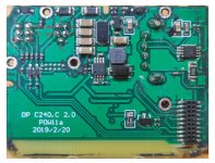
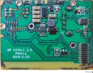
See the pictures of the inside of that display, on the repository: https://github.com/OpenSourceEBike/Bafang_M500_M600/blob/main/Hardware/display_DP_C241.mdTomblarom said:Anybody opened up the DP-C241 or knows, whether the BT-module is separately attached or they use an nRF instead of STM32 on them? Don't want to kill mine if this there is info about it... :lol:


Tomblarom said:Anybody opened up the DP-C241 or knows, whether the BT-module is separately attached or they use an nRF instead of STM32 on them? Don't want to kill mine if this there is info about it... :lol:
Waynemarlow said:The M600 will run fine on just a simple + -. A few of us have made 21700 batteries and they work fine, in fact very well. My 48 volt unit will start up on the 58.4 volts my charger takes the battery to. I like the 52 volts as the cadence is more like a proper mtb rather than the low speed torque of some of the mid motors.
But the displays will only display battery volts and not the peripheral calculated mileage to go etc. Some displays will show W/hs used so I guess thats just an onward going calculation.
Can you please follow the connections and components about the V+ and VBattery pins??CiDi said:The photos on the reposity are of my DP-C241.


casainho said:Can you please follow the connections and components about the V+ and VBattery pins??CiDi said:The photos on the reposity are of my DP-C241.
We need to know what happens to that both signals and the interaction with the power button. Maybe you could follow the connections of the wires and see what type of components there are and the connections. I think you can measure the resistors with a multimeter.
For instance, that 2 traces are probably from V+ and Vbattery - are that resistors or capacitors? and any of that signals go to that mosfet? and is any of the mosfet signal go to the STM32F103? The middle pin of the mosfet seems to go to GND trace.
And here we see resistors in series with every wire, and then 2 diodes. One diode has common path to 2 pins of different connectors.
I need to know how pressing the on/off button changes the VCC from Vbattery to 2.2V or 4.5V.CiDi said:I signed the pins, what do you need to know?
casainho said:I need to know how pressing the on/off button changes the VCC from Vbattery to 2.2V or 4.5V.CiDi said:I signed the pins, what do you need to know?
Please follow the traces to see the VCC trace and what changes on the traces of on/off button that will then change the Vbattery.
Can you measure all the 5 resistors in parallel paths?
See that there is an inductor and IC near, and with array of 4 capacitors in parallel. That are for sure the DC-DC that will take the battery voltage to output 3.3V for the microcontroller, etc.
casainho said:Please draw colors on the traces, so we can understand where they go. Change the color when there is another component on the path, like that resistors. Measure the values of each that resistors, maybe you can number them and say here their value. For now, let's focus on the Vcc pin and on/off pin.