Battery pack cells vs construction and voltage sag

E-HP

10 GW
Joined
Nov 1, 2018
Messages
6,410
Location
USA
I probably should post this in the battery section, but maybe something discussed here in the past...when it comes to voltage sag for a given pack, how much sag, if any, can be attributed to poor pack construction (other components used for constructing the pack, etc.) versus cell choice? This is assuming the cells are all tested and matched. For example, two pack builders use the same quality cells, but the components they use (nickel/copper strips, etc.) or construction technique (spot weld, solder, bolt together holders, etc.), is there a difference in the voltage sag under load?

I guess a few follow up questions, if there is a significant difference, are, is it safe to assume that voltage sag due to construction of the pack when near LVC isn't actually harming the cells, when they are above LVC, so I'd only be concerned with the additional heat from the underated strips? Can a pack be retrofitted easily to remove the bottlenecks from poor construction?
 
A pack with poor connections will have more resistance so will have bigger voltage drop all the time, won't it? Just like if you wired a light up to a power source and stuck a resistor in-between. Light gets dimmer. V = IR. Increasing R increases the voltage drop even if the current, I, stays the same.

Voltage sag due to excessive discharge comes in when you are discharging higher amps than the cells are rated for. So that's more situational. It happens particularly when accelerating or going uphill and the controller decides to increase the current drawn.

Poor connections will also generate heat. Hopefully the pack has a good BMS that will cut off discharge if a temperature probe indicates the pack is heating up too much. Too much heat can trigger thermal runaway - fire. A good BMS will cut off discharge for thermal events, not just when the first p-groups reaches LVC.
 
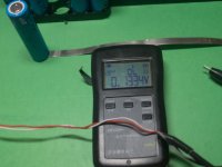
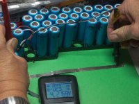
I think that most of the sag appears in the cells. You may critique my analysis. I measured a cell at 12.3 milliohms of internal resistance using my YR1035 meter. This is actually an AC impedance via a four point probe, but it still has to see parasitic resistance between the probes.

I tacked 6 inches of 10 mil wide .20 mm nickel on the bottom of the cell. Retook the IR at the near end of the strip to verify I still had 12.3 milliohms. Walked the probes down 6 inches and measured 23 milliohms, So the 6" of nickel is about .010 ohms. Now we never see anything that long in a battery, maybe a 3/4" run of nickel, and they will be in parallel, So I believe the nickel can be ignored.

What's left is perhaps a foot of 14G wire?


P1650713.JPG fP1650717.JPG
 
Last edited:
I think that most of the sag appears in the cells. You may critique my analysis. I measured a cell at 12.3 milliohms of internal resistance using my YR1035 meter. This is actually an AC impedance via a four point probe, but it still has to see parasitic resistance between the probes.

I tacked 6 inches of 10 mil wide .20 mm nickel on the bottom of the cell. Retook the IR at the near end of the strip to verify I still had 12.3 milliohms. Walked the probes down 6 inches and measured 23 milliohms, So the 6" of nickel is about .010 ohms. Now we never see anything that long in a battery, maybe a 3/4" run of nickel, and they will be in parallel, So I believe the nickel can be ignored.

What's left is perhaps a foot of 14G wire?


View attachment 330919 fView attachment 330920
I think the parameters may not be static. Using a 20S1P 18650 pack for an example, With no load, the voltage divider looks like the internal resistance of 20 cells in series, and the resistance of 342mm (18mm x 19) of nickel strip (or whatever material the cheap pack is using). If the pack was built correctly, the nickel strip can carry the required current continuously, and have very little contribution to sag. A poorly constructed pack could have poor connections/welds and inadequate strips (nickel plated steel vs. nickel, not enough layers, etc.). So that means more heat and as heat goes up, so does resistance. Might still be insignificant, but seems like there are more things to consider.
 
A 20s pack of 1mOh cells for me.. reads about 23-26mOh when assembled. That means the entire bus is 3-6mOh. From positive to negative lead.

On a cold cold day that might increase to 30mOh. The IR increases in the cells not the bus. When cold Bus is still 3-6mOh.

Negligible if you build it right. A good contactor ( 200A ) might be 0.6mOh,... a rally good one ( 800A) is like.. 0.2mOh... when the single cell is 5x that ( 1mOh).. so its really negligible.

1mOh cell does not sag alot.... Its like a 10p group of Molicell P42A... (10mOh ea) .. my cells are dead on 1mOh ea. So every string is 1mOh. So there is 20 mOh in the pack, and 3-6mOh in the entire bus.

Not alot of heat created through milliohms.
Just to understand, if the assumption is that the pack is poorly constructed and the strips used are underrated, is there no benefit to retrofitting the pack to remove any bottlenecks? The strips won't cause any issue as long as the cells have sufficient discharge capacity?
 
Why not take a thermal camera and observe the pack when wired up to a test load? Then you'd be able to see any hot spots that need fixing, if any.
 
Back
Top