Cell Level LVC Prototype: 30V - 150V @ 80A (pics)

methods

1 GW
Joined
Aug 8, 2008
Messages
5,555
Location
Santa Cruz CA
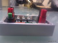
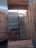
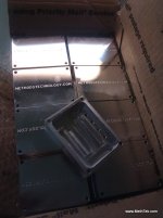
I recently had a very interesting fellow come by the shop. We got to talking and decided machine up a batch of 50 aluminum housings that will allow us to re-purpose my HVC Breaker module into a Pack Level LVC Cutoff.

30V - 150V+ operation
~80A continuous current (this is somewhat arbitrary... I figure a bike might see peaks to 120A with an average of less than 50A)
Isolated housing that is fully encapsulated in epoxy
0uA draw after being tripped

This was our first prototype
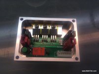
IMG_20120526_205911.jpg
View attachment 1
IMG_20120526_205924.jpg

The idea would be to then fill in the void with epoxy.

After much talking and thinking about what the Motorcycle guys and ebike guys would want - we have changed our plans. The final product will be similar to what is above, but with the following changes:

* Board mount Andersons replaced with 10AWG silicone pigtails exiting out the side (controller style)
* Board mount button replaced with connectoized button (for relocation)

So as we stand today there would be a slot on the left or right side of the board.
The tentative plan is to line that slot with silicone, lay the wires in, lay another bead of silicone, then put the top on for curing. After the silicone has cured we will backfill the entire volume with epoxy. Purpose of the silicone being only to stop the epoxy from weeping out during potting. We want to avoid hot glue... but that would be another option.

For those seeing this for the first time - this module plugs into a hardware LVC/HVC detection system I have. If any one cell hits 3.0V this module would then break the battery connection in your system and lower system current draw to 0uA (it cuts its own power with a latching relay). That is the ebike application...

For the motorcycle guys they will want to place this between the charger and pack to have a high voltage, high current, high reliability HVC protection module that can terminate charge if any cell goes above 4.29V. Since many of them are running 1000A+ all of the HVC/LVC boards have a built in ability to do simple throttle retard.

So... this will be a limited run that I am going to let go at an affordable price. After this we will iron out the details, production-ify the process, and raise the prices to something sustainable.

A lot of you have been asking for something like this - A module that can completely terminate discharge on your battery even in the case where a controller is left on for weeks at a time. This should meet your requirements. At 50A constant discharge the assembly only warmed up by a few degrees C.

-methods
 
To follow up on that (sometimes I forget that you guys dont know everything that is bouncing around inside my head...)

This module can be used for two separate operations:

1) It can go between the charger and the pack to act as HVC protection. If any cell goes over 4.29V it will blow open and terminate charge.
2) It can go between the pack and the controller to act as LVC protection. If any cell drops below 3.0V it will blow open and terminate discharge.

It is triggered by an opto input - so basically anything that can short two wires together (may be compatible with anything you have that has an opto out)

It latches in the triggered state and turns its own power off to drop current draw down to 0A. It can then be reset with the button.

I swear I need to actually write some of this stuff down one day :)

-methods
 
Looks very neat indeed. Only observation I'd make would be to use PU rather than epoxy for potting. Clear PU remains slightly flexible and tends to move enough to allow components to expand and contract without cracking. I had problems years ago when I encapsulated some power stuff in epoxy, so tend to now use the flexible potting stuff whenever I can.
 
Thanks Jeremy - that is exactly the kind of feedback I was hoping to get. I will look into it for sure.

new subject:
On an email someone was just asking about having these modules work bidirectionally to terminate both charge and discharge in one unit. This is easy enough and the next version will do it... but we thought it better to just move forward with what we had working/tested in hand then to try and hold off for another PCB spin. The bi-directional deal requires a slightly more tricky biasing scheme for the fets in the reverse direction. The way I handle this on my BMS is to (just cheat) and use an isolated $3 DC-DC module. Trouble is those buggers need to run at very high power - like 1W. The total draw of this board as it sits is closer to 10uA... and although I am a competent engineer - I am not yet quite good enough to handle the bi-direction control without either increasing the current draw or greatly increasing parts count.

Up until now I have treated parts count as our #1 driver... with power consumption being a close second. But... now that we are solder pasting and looking much more seriously at Pick and Place - adding another 5 or 10 parts to the board is not nearly as intimidating. I am thinking I could do a little boot strap circuit. High in parts count but low enough power.

-methods


Jeremy Harris said:
Looks very neat indeed. Only observation I'd make would be to use PU rather than epoxy for potting. Clear PU remains slightly flexible and tends to move enough to allow components to expand and contract without cracking. I had problems years ago when I encapsulated some power stuff in epoxy, so tend to now use the flexible potting stuff whenever I can.
 
Yep - epoxy encapsulation of anything that gets hot does run the risk of component lead fractures etc as well. And when you let the magic smoke out, its really hard to get it back in there :)

Also - where did you get the board mount andersons? Or did you make these up yourself with solid copper crimped to them?
 
methods said:
(sometimes I forget that you guys dont know everything that is bouncing around inside my head...)

Oh, but we do! And it ain't pretty... :twisted: Those pesky voices that you've been hearing have been tweeting everything!
 
heathyoung said:
Also - where did you get the board mount andersons? Or did you make these up yourself with solid copper crimped to them?

There are three basic flavors.

Stubby high current
Beefy right angle high current
Pokey right angle (PCB)

http://www.powerwerx.com/anderson-p...printed-circuit-board-pcb-45-amp-contact.html
pcb45_xlrg.jpg


http://www.powerwerx.com/anderson-p...rinted-circuit-board-pcb-25-amp-contacts.html
pcb25_xlrg.jpg


But what you suggested would work perfectly fine. :)

Since we are on the subject... if anyone here is serious about adopting the Anderon convention dont waste any time. Just buy this crimper.

http://www.powerwerx.com/powerpole-accessories/tricrimp-crimping-powerpole-contacts.html
TRIcrimp2_xlrg.jpg


I have crimped literally thousands of PowerPoles with that $40 tool and it is the best thing on the planet. You buy the big 10awg 45A contacts and they are perfect for Hobby King wire. YOu then also get the 30A and 15A for smaller projects. Buy every color of plastic housing, make up keying conventions, and stick to them. Everything I have is now on Anderson and I absolutely love it.

Back in the day I was on Deans connectors... what nightmare that was. :roll:

since I am on my soap box... I used to be a die hard solder guy - but now I crimp every chance I can get. There is nothing better than a professionally crimped connection that comes from a properly tuned ratcheting crimper. (IMHO) Airplane guys will disagree (I mean real airplanes) and that is the one application that I would actually solder too.

-methods
 
methods said:
since I am on my soap box... I used to be a die hard solder guy - but now I crimp every chance I can get. There is nothing better than a professionally crimped connection that comes from a properly tuned ratcheting crimper. (IMHO) Airplane guys will disagree (I mean real airplanes) and that is the one application that I would actually solder too.

Crimp AND Solder!

Avoid using solder as the electrical connection, it should be there to help ensure the mechanical connection remains solid.
If you're going to pick just one, absolutely crimp. Most people consider a horrible cold joint covered in heat shrink to be 'soldered' and wonder why they melt connectors.

I find Anderson Power Poles to be about the best multi-purpose connector ever made, at least when assembled right.
 
There is a theory that soldering crimped join actually reduces its mechanical strength by making it too rigid and inflexible, I should check what the IPC standards book says on that, now that I think about it
 
Looking good, my man! I'm always a proponent of machined aluminum bits.

If I were designing/machining the box I would put radii on the outside corners just to make it a little less likely to poke anything around it- depending on how the box was fixtured (can't quite tell from the photos) this might require more steps, or it could be totally free. If the latter, I would do it. If the former- eh, maybe.

Methods- for that new revision, you know, the "screw the parts count" version... I'm sure you've realized you've pretty much built the "soft-start main power switch" here too. If this could do both LVC/HVC breaker function and soft-start on/off the money would FLY out of my pocket for it. Seems to me you could do that just by adding another momentary button that "trips" the breaker- then you have an off button (the trip switch) and an on button (the existing reset switch)... I think that would be really handy.

Hm, point of clarification- will the current design working as a HVC breaker be OK running bidirectional current from a regen controller? It just won't trip if the HVC limit is hit under regen?

As for the good old to crimp/to solder debate- a good crimp wins- solder will wick into the strands of the cable and make the joint more likely to fatigue and fail. A well crimped joint should be essentially forged/welded together and impervious to internal corrosion. I would expect that real aircraft are wired only with crimped joints, given the criticality of proper attention to metal fatigue in planes. The flight computers for the Apollo spacecraft were not soldered- they were wire wrapped. Since buying proper crimpers for the various different connectors I use I haven't soldered a single connector pin.
 
acuteaero said:
Looking good, my man! I'm always a proponent of machined aluminum bits.

If I were designing/machining the box I would put radii on the outside corners just to make it a little less likely to poke anything around it- depending on how the box was fixtured (can't quite tell from the photos) this might require more steps, or it could be totally free. If the latter, I would do it. If the former- eh, maybe.

I will ask him - or I suppose he will probably read this

Methods- for that new revision, you know, the "screw the parts count" version... I'm sure you've realized you've pretty much built the "soft-start main power switch" here too. If this could do both LVC/HVC breaker function and soft-start on/off the money would FLY out of my pocket for it. Seems to me you could do that just by adding another momentary button that "trips" the breaker- then you have an off button (the trip switch) and an on button (the existing reset switch)... I think that would be really handy.

Never crossed my mind since I rarely disconnect my battery from my controller. I like it though - good idea and easy. The capability is already built in and ready to go. All you have to do is tap in a button between the LVC_GND line and LVC_Signal line. I suppose I could put an extra pair of holes in the PCB or maybe offer a custom wiring harness with this pair coming out as a JST SM. I actually have a cap on the board that is in parallel with the gate of the fets that would add a nice slow rise time - but I dont populate that cap. Rise time is quick - but once the connection is made that should be fine.

Thanks for the idea :wink:
I really appreciate it when folks point stuff like this out. I guess my head is just in the clouds these days... but that is definitely a feature we should further incorporate.

...
Hm, point of clarification- will the current design working as a HVC breaker be OK running bidirectional current from a regen controller? It just won't trip if the HVC limit is hit under regen?

The HVC breaker is only between the pack and charger so even if it did hit it would not affect discharge. I have HVC set to a lofty 4.29V which is pretty high... I highly doubt anyone will go that high with regen. I mean - it is ok to hit that kind of dynamic voltage so long as the resting voltage is within reason... I just did not think anyone actually would.

Getting more to your point - when the mosfets are activated they can pass current in either direction equally well. The only nasty bit is that if they are triggered (lets consider the unit between the battery and controller) they can only *block* current in one direction. So in this case if somehow LVC tripped while in regen then regen would continue to happen right through the body diode of the fet. That wont hurt anything (for short periods) and it is sort of good in that a person wont suddenly lose their regen braking without warning

Now... on the second version this would not be the case. If LVC were tripped (say - via noise or via an inadvertent button press) then regen would instantly terminate. I dont think we need to worry about that for now though. The way I designed it - the HVC and LVC are completely isolated circuits.... and that is why I have a mess of 6 wires running down my daisy chain (instead of 2 or 3).


As for the good old to crimp/to solder debate- a good crimp wins- solder will wick into the strands of the cable and make the joint more likely to fatigue and fail. A well crimped joint should be essentially forged/welded together and impervious to internal corrosion. I would expect that real aircraft are wired only with crimped joints, given the criticality of proper attention to metal fatigue in planes. The flight computers for the Apollo spacecraft were not soldered- they were wire wrapped. Since buying proper crimpers for the various different connectors I use I haven't soldered a single connector pin.

I would tend to agree with those statements.

thanks,
-methods
 
Yes, it should be possible to make this into sort of a "solid state contactor", something I have been looking at for a while. I'm not sure what would happen if you just slam on the FETs against a fully discharged main capacitor bank in a controller. High peak current for sure, but not sure if it would be in the destructive range.
The idea here is to eliminate the big spark you get when connecting a pack to the controller for those who frequently disconnect the battery.

A slow rise time could be self destructive if there is a heavy load other than just charging some caps. Ideally, you'd want a separate precharge circuit and turn on the main FETs only after the caps have reached charge, thus inhibiting turn on in the event of a shorted controller. This is probably too complicated for how often it would happen.

The design I was working on would have a remote switch that could be on the bars or easily accesible spot that could be used as a main on/off switch, combined with LVC active cutoff. This switch would also reset the device in the event of a trip.

To make it work both for charge and for discharge, you could use twice the silicon in a back-to-back arrangement, but then your losses (heat) are doubled. There are some level-shifting problems associated with this setup as well. It might make more sense to have separate charge and discharge connections so that the discharge path only goes through one set of FETs.
 
fechter said:
A slow rise time could be self destructive if there is a heavy load other than just charging some caps. Ideally, you'd want a separate precharge circuit and turn on the main FETs only after the caps have reached charge, thus inhibiting turn on in the event of a shorted controller. This is probably too complicated for how often it would happen. .

I think Mr. Fetcher is right- a real robust precharge is more complex- and the ability to sense a dead short (or great load) downstream (when the precharge takes too long- voltage is increasing too slowly) is a great advantage- But, on the ebike we certainly like things as simple as we can have them while keeping them reasonably robust- so, let's say we turn on the FETs in 1/20th of a second... will the heat that is generated in them turning on into a constant dead short, and until the main fuse blows be enough to kill the breaker device? Better have a good fuse in there. If we switch the FETs on in 1/20th of a second and have a bank of high power halogen spotlights attached directly to its output will they generate enough heat going through their resistive area to hurt themselves?

I personally really like the super simplicity of the previously proposed approach- and as far as I have imagined it should work pretty well in most cases, as long as a pack fuse is present. Some good logic to run the precharge would be cool, but I think not at the expense of super simplicity. Tradeoffs!!!

I think I would probably add a controller cap bleeder/power on indicator light to the controller side, but that can be done outside of the breaker device. That would make an ideal system to me.

Fun fact: "activating" my prius with 3kw of Mean Well power supplies attached directly to the controller side of the HV contactor caused a precharge fault, complete with BIG RED DASHBOARD TRIANGLE OF DEATH
 
Awesome work! They look very nice. Having one unit be able to have charge AND discharge protection would be ideal.
 
For a slow start/pre-charge switch you don't need fancy fault protection, just add a big fuse in the power lead. The switch FETs will tolerate high continuous current for long enough to blow the fuse under a true fault condition, as they will need to be rated for low power dissipation when running at normal loads, giving them a massive reserve for relatively short duration high current events.
 
Nice job Patrick, very similiar to my Smart Switch design. I used a controller so I could add more features. Take a look at it, it gets rid of the sparking problem as well and shuts down the packs after a predetermined delay. I've even added a fuel guage for the scooters I built for my nieces. I avoided the heatsink issue by turning the Fets fully on and allowing more to be installed to decrease on resistance.
 
I always like the things that you design. :)

I recognize that latching relay you have in there. Smart way to do it... I did not see your stated continuous current draw but it does not matter if your device is smart enough to shut itself down completely. Very clever! That is basically how I designed my BMS V3.0 and V4.0.... it can power up automatically with the attachment of a charger but once that charger is removed it can continue to draw power as long as it needs it - then once the cells are balanced it commits suicide. I did it with some back to back mosfets and a second 400V mosfet to control it - I will post the schematic if anyone cares. The latching relay is a lot easier though.

You might have a look at the part number I used - I think they are quite a bit cheaper than the relays you chose. I dont know how you are driving your coils but what I basically did was to run the relay coil current through the relay contacts... then I just use a current limiting resistor and tie directly into the input voltage (be it 30V or 130V). The coil then gets hit either soft or hard - but in any case as soon as the coils are energized enough to move the contacts it cuts its own power. :mrgreen: This way even if the user holds down the reset button it cant overheat the coils and it greatly simplifies the coil driving circuit (400V mosfet and a resistor) and expands the operating range.

It would be great if more people could have your stuff and I particularly appreciate that you post up the details of your designs and offer raw boards to the DIY members. That is awesome.

I have my new Arduino nano ebike shield sitting on the shelf over here... we already have 3 solid profitable applications for it but I would also really like to open it up to folks who want to tinker. I am thinking a lot more people will be able to break into the Arduino code than PIC ASM or C.... anyhow... I think I need to go back and redesign. To hell with power draw - I will draw as much as I please and when I detect that the bike is no longer in operation I can just time out and cut my own power.

oh boy oh boy oh boy...

It is weird how you can "know something" and not even realize it until you see someone else do it... you know? I mean I was already doing exactly what you are doing with my BMS but it never occurred to me to do it with my other products.

Thanks for the link!
(as methods sneaks off to steal your awesome ideas ... :p )

-methods
 
Ha ha, no problem. Who better than another ebiker and techno geek. Glad you found it useful. Too bad you don't live next door.
 
How about lucky we have this forum to collude on.
Remember cracking open an encyclopedia as a kid? Phffftttt... we are living the dream in the wild west here. Enjoy it while it lasts.

-methods
 
IMG_20120626_170840-001.jpg
IMG_20120626_170848-001.jpg


I am going to start out by just offering an upgraded HVC Breaker module. As time permits we will get some LVC testing in and perhaps make 10 of them available for testing. Matthew has 50 of the boards in production right now - waiting on parts from Digikey and Mouser.

We made a change to the gate driver - 10M resistor swapped out for 5M. Not enough zener current to reliably kick on the mosfets. This means that our waste current is going to double from around 10uA to 20uA.... but it does not matter all that much since it gets mechanically turned off once an LVC event occurs.

How you like dem pretty boxes eh?

-methods
 
I'm sure I need one of those gizmos, just for the box art alone. What did you say that thing does............................................................................................................................ :)?
otherDoc
 
docnjoj said:
I'm sure I need one of those gizmos, just for the box art alone. What did you say that thing does............................................................................................................................ :)?
otherDoc

That is exactly how I feel about it :)


ZOMGVTEK said:
...Do you have a 200A model?

We could definitely do a 200A ebike model... like something that just sees peaks of 200A. I would not use it on a motorcycle or car though that sees 200A continuous as the wire heating alone starts to become a chore.

If we are talking about a bicycle application where you pull 200A for a few seconds and then settle out to a much lower average - yea - I would just run dual 10AWG into the case and double up on the mosfets. It would be hacky but under the epoxy you would never know it.

What was your application?

Another concern is dealing with the blow-back when the circuit breaks. Breaking 200A 100V can cause some serious noise.

-methods
 
Methods,

I have read all of your documentation, and lots of your posts about Lvc hvc... I am looking to build a pack with 6s nanotechs. For a 111v nominal 20ah pack for my krazy ekart. It will peak at 500 to 600 amps for no more than 10 to 20 seconds at a time, never over 50kw. It looks like I could use some of your parts for paralleling to cell level, but the lvc will not handle this much current right? The new beefy hvc looks like it will work to charge each 10ah module at 50amps each with separate chargers? Any recommendations or mods to your system or any other for lvc?

Thanks,
Brock
Www.winzeracer.com
 
Back
Top