E-bike with lost connection between motor and battery

Cyclomania

10 kW
Joined
May 22, 2022
Messages
514
Location
Northern Europe
Hi

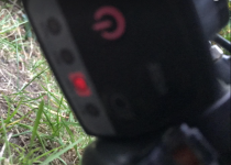
So I have an ebike that has a functioning battery. The 36-volt battery gives current to the display of the ebike. But the connection between the motor and the battery seems to be lost. Why this is happening is a mystery :)

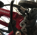
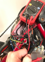
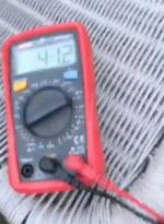
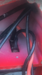
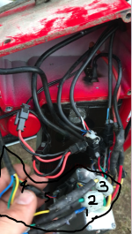
As you can see from the pictures, I have opened up the box below close to the pedals, where the controller sits, and I have measured current there going from the connection, from the inside of the bike's screwed up box. And it seems on the multimeter that the battery is giving current into the controller, since the multimeter is measuring 41-42 volts there, right below where the battery is connected to the bike.

And from here on I would like to get some help. Because looking at the other cables I don't quite know what and how to measure if there is current going into the motor.

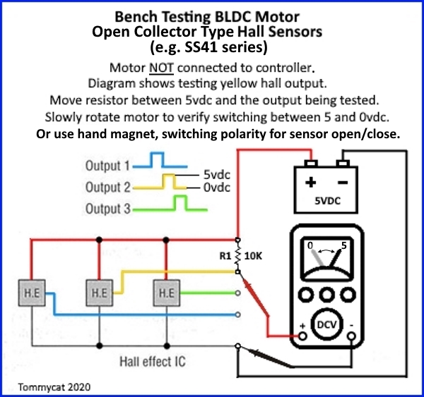
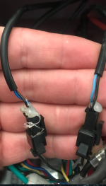
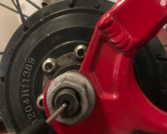
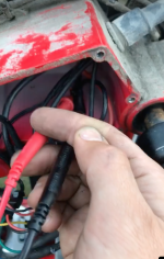
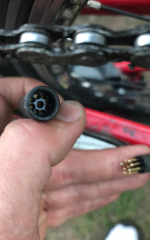
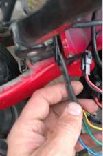
The Julet connector from the motor I am not sure about how to measure. Is it possible to measure plus and minus inside of that with the multimeter somehow? And if so how? There are several little holes in that Julet connector and I don't know what is plus and minus or if that is a possible alternative ?

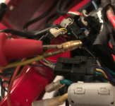
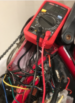
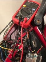
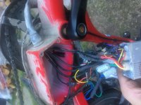
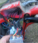
Also, from the controller to the motor there are several cables, with many different colors. And I am not sure how to find the issue going forward. Any suggestions? How do I measure the current(or non existent current) going from the controller to the motor with the multimeter? (If you think that is the problem). And if it could be something else, please let me know.

Seems to be around five cables going from the controller to the motor. But only the black and red going into the controller, to give it current. So I am not sure about how to measure current going out of the controller. Or to see if the controller might have some issue inside of it.

Here is a video:

https://www.veed.io/view/03e9d4f0-1b59-4fcf-a52c-fc3df06687b8
 

Attachments

  • Skärmavbild 2022-08-13 kl. 21.45.38.png
    Skärmavbild 2022-08-13 kl. 21.45.38.png
    892.5 KB · Views: 864
  • Skärmavbild 2022-08-13 kl. 21.45.57.png
    Skärmavbild 2022-08-13 kl. 21.45.57.png
    589.2 KB · Views: 864
  • IMG_0755.JPG
    IMG_0755.JPG
    2.2 MB · Views: 861
  • Skärmavbild 2022-08-13 kl. 21.55.28.png
    Skärmavbild 2022-08-13 kl. 21.55.28.png
    404.5 KB · Views: 861
  • Skärmavbild 2022-08-13 kl. 21.53.35.png
    Skärmavbild 2022-08-13 kl. 21.53.35.png
    862.4 KB · Views: 861
  • Skärmavbild 2022-08-13 kl. 21.54.17.png
    Skärmavbild 2022-08-13 kl. 21.54.17.png
    2.3 MB · Views: 861
  • Skärmavbild 2022-08-13 kl. 21.55.15.png
    Skärmavbild 2022-08-13 kl. 21.55.15.png
    1.1 MB · Views: 861
  • Skärmavbild 2022-08-13 kl. 21.58.32.png
    Skärmavbild 2022-08-13 kl. 21.58.32.png
    2.3 MB · Views: 861
  • Skärmavbild 2022-08-13 kl. 22.09.57.png
    Skärmavbild 2022-08-13 kl. 22.09.57.png
    1.1 MB · Views: 853
  • Skärmavbild 2022-08-13 kl. 22.10.07.png
    Skärmavbild 2022-08-13 kl. 22.10.07.png
    867.7 KB · Views: 853
E-HP said:
E-driver_ said:
No it does not. It does sometimes though. Perhaps every 60th try or so. So nothing happens for 59 tries and then all of a sudden it might give a little wheel power for two-three seconds. What might this be an indication of?

I wouldn't limit your testing to the controller, but test the phase wire and halls of the motor. The behavior above indicates that no one component has completely failed, but partial failure of one or more components, that somehow the working parts magically align to allow the bike to runs for a few seconds every 60th try. Perhaps a bad phase winding and a couple of fried halls, that took out some Mosfets when they failed. Who knows. Something doesn't add up, especially that the bike just stopped running out of nowhere and not under high loads, etc.

Yeah I haven't tried the brake sensors either. Perhaps the magnets there have gone fishing or something ?

The phase wire is the wire going from the controller that connects to the motor right?

Hall sensor is located inside the motor ?
 
E-driver_ said:
E-HP said:
E-driver_ said:
No it does not. It does sometimes though. Perhaps every 60th try or so. So nothing happens for 59 tries and then all of a sudden it might give a little wheel power for two-three seconds. What might this be an indication of?

I wouldn't limit your testing to the controller, but test the phase wire and halls of the motor. The behavior above indicates that no one component has completely failed, but partial failure of one or more components, that somehow the working parts magically align to allow the bike to runs for a few seconds every 60th try. Perhaps a bad phase winding and a couple of fried halls, that took out some Mosfets when they failed. Who knows. Something doesn't add up, especially that the bike just stopped running out of nowhere and not under high loads, etc.

Yeah I haven't tried the brake sensors either. Perhaps the magnets there have gone fishing or something ?

The phase wire is the wire going from the controller that connects to the motor right?

Hall sensor is located inside the motor ?
Yes. Here's some info for testing:
https://electricbike.com/forum/forum/kits/golden-motor-magic-pie/110168-testing-bldc-motor-s-phase-wiring-hall-sensors-and-wiring
 
e-beach said:
No voltage required. You are checking for continuity, not voltage.

However lets shift gears a little.

Set your DMM to 20kΩ. Put the red prob into the black battery connector of your controller, and put the black probe to one of your controller phase wires.

look for a reading. (a number)

Then move the black probe to the other phase wires and see if you get a reading

If you get a 0, then you have a short in a mosfet.

I tried this. And.. I have continuity! Because it showed a reading of around 1 when I did this. So perhaps it is not the controller that is blown after all?
 
E-HP said:
E-driver_ said:
E-HP said:
E-driver_ said:
No it does not. It does sometimes though. Perhaps every 60th try or so. So nothing happens for 59 tries and then all of a sudden it might give a little wheel power for two-three seconds. What might this be an indication of?

I wouldn't limit your testing to the controller, but test the phase wire and halls of the motor. The behavior above indicates that no one component has completely failed, but partial failure of one or more components, that somehow the working parts magically align to allow the bike to runs for a few seconds every 60th try. Perhaps a bad phase winding and a couple of fried halls, that took out some Mosfets when they failed. Who knows. Something doesn't add up, especially that the bike just stopped running out of nowhere and not under high loads, etc.

Yeah I haven't tried the brake sensors either. Perhaps the magnets there have gone fishing or something ?

The phase wire is the wire going from the controller that connects to the motor right?

Hall sensor is located inside the motor ?
Yes. Here's some info for testing:
https://electricbike.com/forum/forum/kits/golden-motor-magic-pie/110168-testing-bldc-motor-s-phase-wiring-hall-sensors-and-wiring

Great. But that post was a bit hefty. Is it any post about testing of the hall sensors and phase wires for dummies out there? Like it was for the throttle and mosfets? I think I will have to study that thread over the weekend because it was a lot of information in there to learn before testing :bigthumb: But many thanks. I need to learn this
 
E-driver_ said:
E-HP said:
E-driver_ said:
E-HP said:
I wouldn't limit your testing to the controller, but test the phase wire and halls of the motor. The behavior above indicates that no one component has completely failed, but partial failure of one or more components, that somehow the working parts magically align to allow the bike to runs for a few seconds every 60th try. Perhaps a bad phase winding and a couple of fried halls, that took out some Mosfets when they failed. Who knows. Something doesn't add up, especially that the bike just stopped running out of nowhere and not under high loads, etc. The diagram below show the lead placements for testing the yellow hall sensor.

Yeah I haven't tried the brake sensors either. Perhaps the magnets there have gone fishing or something ?

The phase wire is the wire going from the controller that connects to the motor right?

Hall sensor is located inside the motor ?
Yes. Here's some info for testing:
https://electricbike.com/forum/forum/kits/golden-motor-magic-pie/110168-testing-bldc-motor-s-phase-wiring-hall-sensors-and-wiring

Great. But that post was a bit hefty. Is it any post about testing of the hall sensors and phase wires for dummies out there? Like it was for the throttle and mosfets? I think I will have to study that thread over the weekend because it was a lot of information in there to learn before testing :bigthumb: But many thanks. I need to learn this
This diagram in the article is all you need for testing the hall sensors. Your motor has a harness with thin and thick wires; the thick are the phase wires, and thin are the halls. With the motor disconnected, you will be testing using the small wires, by applying 5V to the red and black, then measuring each hall sensor by the voltage between the black and yellow; black and green; black and blue. You do this by placing the probes on those pairs and slowly turning the wheel/motor, which should result in an alternating 5V/0V as you turn, if the halls are good. Test the three pairs, if any don't alternate back and forth, something is wrong with the hall sensor, or the wiring in between.
NktFBwJ.jpeg


For testing the phase wires, I'm not sure anyone could explain it any better than the section titled Motor Winding Testing.
 
E-driver_ said:
[...I tried this. And.. I have continuity! Because it showed a reading of around 1 when I did this. So perhaps it is not the controller that is blown after all?

Do the other phase wires read the same as the one you are describing?
Be sure to test all the phase wires and write your results down.

If you are not sure about your e-brakes, unplug them from the controller to disable the signal from them.

Also. it is possible to do the motor hall sensor testing while the wheel is on the bike.
First read this:https://ebikes.ca/documents/HallSensorTestingFinal.pdf

Then watch this video.
[youtube]efYFOHnXh0E[/youtube]

Then plug in all your wires and do what is described in this video.

Once you have done the hall sensor test, let us know.
 
e-beach said:
No voltage required. You are checking for continuity, not voltage.

However lets shift gears a little.

Set your DMM to 20kΩ. Put the red prob into the black battery connector of your controller, and put the black probe to one of your controller phase wires.

look for a reading. (a number)

Then move the black probe to the other phase wires and see if you get a reading

If you get a 0, then you have a short in a mosfet.

Now I have done this to all three phase wires on the controller side. And they all had a reading of about 9,46-9,47.

I have also disconnected the brakes and tried to tape a magnet to the sensors there below the brake handles. No difference.

Now I am going to proceed and read about the Hall sensor testing and all that stuff during the weekend. I will keep you updated
 
I have done the simple Hall testing now of the hall cables and the probes. They all turned between 0 and 5(4,7 really).

BUT.. The blue one only got up to about 3,2 when turning. So perhaps something wrong with that one?

It is switching. But on the high side only goes to 3,2. Not 4,7 like the green and yellow.
 

3.2 is a bit weak, but the bike should still run if maybe a bit juddery at the start.

So connect all your wires together again with the exception of the e-brakes and see what happens. Make sure your throttle connector is fully seated.
 
Oh, one more thing before you plug the phase wires into your controller. Set your meter to continuity, tough the probes together to make sure it beeps, put one prob into a phase wire from the motor and push the other on into your motor axle. You may have to press hard to get a proper contact. See if you have continuity. Do this with the other two phase wires as well.
 
e-beach said:
Oh, one more thing before you plug the phase wires into your controller. Set your meter to continuity, tough the probes together to make sure it beeps, put one prob into a phase wire from the motor and push the other on into your motor axle. You may have to press hard to get a proper contact. See if you have continuity. Do this with the other two phase wires as well.

Hmm ok. Here I should have it set to diode correct? And no battery connected? Or is this like the Hall sensor testing where the battery should be connected?
 
We are testing your motor stater this time.

Battery disconnected.

Disconnect the three phase wires from the controller. (the big wires from the motor)

Set you meter to continuity (diode mode) and touch the two meter probes together to make sure it beeps.

Then.....Put your red probe into one of the phase wires and press the black probe to the end of the axle.

You are looking for continuity (the meter should beep)

You may have to scrape the tip of the probe back and forth on the axle to get contact due to the conditions the axle have been through (oxidation, mud ect.)
 
e-beach said:
We are testing your motor stater this time.

Battery disconnected.

Disconnect the three phase wires from the controller. (the big wires from the motor)

Set you meter to continuity (diode mode) and touch the two meter probes together to make sure it beeps.

Then.....Put your red probe into one of the phase wires and press the black probe to the end of the axle.

You are looking for continuity (the meter should beep)

You may have to scrape the tip of the probe back and forth on the axle to get contact due to the conditions the axle have been through (oxidation, mud ect.)

Is it correct to push it into the motor axle like the picture below?

So far I haven't got any connection. But I am going to probe around a bit more.

The picture below in the middle is what I believe to be the brake sensor cables down where the controller is(since there are two of them). Nothing happened when I disconnected those two.

The picture at the very bottom is how I keep the red wire at what I believe is one of the phase wires coming from the motor side, during the measuring.
 

Attachments

  • Skärmavbild 2022-08-20 kl. 18.20.07.png
    Skärmavbild 2022-08-20 kl. 18.20.07.png
    2.5 MB · Views: 401
  • Skärmavbild 2022-08-20 kl. 18.19.39.png
    Skärmavbild 2022-08-20 kl. 18.19.39.png
    1,011.5 KB · Views: 401
  • Skärmavbild 2022-08-20 kl. 18.22.46.png
    Skärmavbild 2022-08-20 kl. 18.22.46.png
    1.9 MB · Views: 401
As for the phase wires, they are the three big ones. That yellow one you point to might be one of them. As for probing the axle, I would not use the bolt. I would use the other side because you can press the probe into the flat part of the end of the axle because no wires are coming out of it.
 
Also, TommyCat made a good point in a PM to me.

When you are testing for a short in your phase wires by probing one phase wire and then the axle you should not get any continuity unless you actually have a sort.

So proceed as I stated above and let us know if your meter beeps (signaling continuity.)

Thanks TC!
 
e-beach said:
I would use the other side because you can press the probe into the flat part of the end of the axle because no wires are coming out of it.

Okay

The other side of the axle where the sprocket and chain is then, right?

Do I remove the bolt or something to probe into it or something like that? I will experiment a bit.
 
The tip of the axle (the butt of the axle) the flat part of the end of the axle.
 
e-beach said:
The tip of the axle (the butt of the axle) the flat part of the end of the axle.

You mean the flat part of the outer bolt on the other side of the sprocket and chain side? This can show continuity? Basically the axle nut on the other side of where the motor cable exits? Ok I will try that
 
This is how I measured. Let me know if it is correct. The two top pictures show how I have the probes during this test.

The test did not show anything though. No number just OL.
 

Attachments

  • Skärmavbild 2022-08-20 kl. 22.56.45.png
    Skärmavbild 2022-08-20 kl. 22.56.45.png
    1.4 MB · Views: 368
  • Skärmavbild 2022-08-20 kl. 22.56.37.png
    Skärmavbild 2022-08-20 kl. 22.56.37.png
    1.2 MB · Views: 368
By the way. I don't know if this is important but when doing one of the mosfets tests again it was continuity like before.

But on the blue cable it was only 0, while on the yellow and green above 9.

See pictures and let me know if this is important.

The picture at the top shows that the blue cable has only 0 during this measurement of the controller. The other pictures show that the measurement of green and yellow is above 9.

I wanted to do this test again just to make sure before I conclude that the mosfets are not the main issue here.
 

Attachments

  • Skärmavbild 2022-08-20 kl. 23.00.27.png
    Skärmavbild 2022-08-20 kl. 23.00.27.png
    2.1 MB · Views: 367
  • Skärmavbild 2022-08-20 kl. 23.00.09.png
    Skärmavbild 2022-08-20 kl. 23.00.09.png
    2.2 MB · Views: 367
  • Skärmavbild 2022-08-20 kl. 23.00.14.png
    Skärmavbild 2022-08-20 kl. 23.00.14.png
    2.3 MB · Views: 367
When measuring the motor for short, make sure the red probe is going to the motor, not the controller.

Also, if your controller's blue phase wire is 0 then while the other's are 9.... your controller may be blown. (bad mosfet)

The question is how did that happen? (how were you riding it at the time?)
 
e-beach said:
The question is how did that happen? (how were you riding it at the time?)

I got it from another guy and he said that it just started not working one day. That is how he told it to me. I believe him. He just did not want to go through fixing it.

e-beach said:
Also, if your controller's blue phase wire is 0 then while the other's are 9.... your controller may be blown. (bad mosfet)

So that indicates the mosfet is blown? It does not show OL though. Only 0.

Also, on that setting "20 k ohm", I get around 0 when putting the red and black probe together as well.

How do you solve a blown mosfet? Is it possible to fix the mosfet in the controller? Or best to just change controller if that is the case?

I have now tried the blue one again and now it seems to show continuity again. Like the other ones. A bit strange but I guess it indicates continuity(?).

e-beach said:
When measuring the motor for short, make sure the red probe is going to the motor, not the controller.

I have tried this again and I got nothing. I put the red in the axle like the above picture but instead with the red going to the motor axle. Held the black in one of the phase wires going from the motor. No battery on. Have tried diode and the ohm 20-one. But I don't get a reading.
 
The OL (no reading) on the axle is good news. It means that you have no short inside your motor (most likley)

Since all your testing seems to read normal, that bike should run unless you have a bad battery connection.

As for changing a mosfet, yes it could be done if you have a 100w soldering iron and good electronics repair technique. It requires disassembly of the controller to access the circuit board. Removing a lot of solder. Unbolting the bad mosfet from the heat sink, removing it and then replacing it. It is not an easy job but it can be done.

Since everything (except maybe the controller) seems to be working, charge the battery, connect everything except the ebrakes, plug it all back together and see what happens. If nothing happens, wiggle the battery connector while pressing the throttle.
 
Off topic question:
I noticed that some bikes, like this one, have what appears to be a choke on each of the three phase conductors. My assumption is that the manufacturers wouldn't invest in any components that aren't absolutely necessary, to cut costs. So, are those necessary in certain applications (to control electrical noise, etc.), and why in this case?
 
E-HP said:
Off topic question:
I noticed that some bikes, like this one, have what appears to be a choke on each of the three phase conductors.....

I guess the manufacture wanted to stop noise from traveling down the line. Why? I am not sure. Maybe it was cheaper then replacing a noisy controller with a better, more expensive one. Just a guess though.

:D :bolt:
 
Back
Top