How do I test a BMS to make sure its working?

So we know it's a 13S BMS, and it looks like a 52 cell 13S pack.

Don't be using a 14S charger on a 13S pack. You can get away with it if you have a working BMS but it is quite risky. At this stage in your learning curve, don't be using it.

You should also check all 13 series groups for voltage to make sure all in useable spec.Nothing over 4.2V or below 2.7V (I know 2.5 is minimum),

I am with Flippy and Chalo. That BMS ain't working if all of the red wires aren't connected. It's designed to shut off continuity between P- and B- if any of the series voltages are below 2.5V. It will shut off continuity between C- and B- if any of the series voltages exceed 4.2V. Per this spec it doesn''t balance.
https://www.aliexpress.com/item/Waterproof-14S-48V-25A-35A-45A-60A-Electric-Vehicle-Lithium-Battery-Protection-Board-BMS-with-Balance/32842587387.html?src=google&albslr=230310488&src=google&albch=shopping&acnt=494-037-6276&isdl=y&slnk=&plac=&mtctp=&albbt=Google_7_shopping&aff_platform=google&aff_short_key=UneMJZVf&&albagn=888888&albcp=1582410664&albag=59754279756&trgt=296904914040&crea=en32842587387&netw=u&device=c&gclid=Cj0KCQjwwODlBRDuARIsAMy_28V_RSAY1AHC0hriqDxqYMSstwrhDvKUA8WBorw7fjQ7g2ey5EHdgAcaArsUEALw_wcB&gclsrc=aw.ds

Sorry. Even though it's waterproof, if it can't balance, it's not the unit you want to use with a pack that is made up of used cells.
 
I did not address how your BMS uses its cell-wires.

I contradicted a general statement that they aren't used for charging.

Apparently we now know that your BMS indeed only uses them for sensing.

Many chargers use them for balance charging, balancers use them for balancing etc.

But not hooked up they certainly do nothing.

I would start over,

googling and reading several dozens of the most popular past threads on various topics

and ask for detailed advice at each step before buying or doing anything further.

Reliable sources for well recommended products is fundamental, eBay and Ali are full of cr^p otherwise you might as well go to the beach throw your money in the ocean

 
john61ct said:
I did not address how your BMS uses its cell-wires.

I contradicted a general statement that they aren't used for charging.

Apparently we now know that your BMS indeed only uses them for sensing.

Many chargers use them for balance charging, balancers use them for balancing etc.

But not hooked up they certainly do nothing.

I would start over,

googling and reading several dozens of the most popular past threads on various topics

and ask for detailed advice at each step before buying or doing anything further.

Reliable sources for well recommended products is fundamental, eBay and Ali are full of cr^p otherwise you might as well go to the beach throw your money in the ocean


So this BMS only cuts on when cell voltage is within threshold, and off when its not. I thought the balance wires were for preferentially charging because of this video:

[youtube]https://youtu.be/dKD0CIumcZw[/youtube]

He solders the B-, P-, and b1- all together. I asked about it and he said he bypassed the BMS, and only used the charging function. I was under the impression that the BMS would charge each group individually, cutting off current to that group when it was fully charged. I guess *some actually do that, but not this one?

Apparently mine just sense charge, so I'll solder them back on and see where we are.

And by "start over", do you mean buy a new BMS?
 
no, this is a regular bms. it can balance the cells and do all those good stuff you expect from a regular bms.

your explanation of houw a bms works does not jive with the diagram of how the guy in the video does it.

ignore what you think and just follow the diagram to the letter.
 
The BMS circuit gets it's power from the balancing wires, so can't work if they are disconnected.

These circuits monitor each cell's voltage and will trip if any of the cells get too high or too low.

The balancing function turns on a resistor across any cell that reaches the balance threshold voltage (generally around 4.2v). When the resistor turns on, it slowly drains that cell to bring it down to below 4.2v. If the bleeder resistor can't keep up, the cell voltage will keep going up until it reaches the OVP voltage and turns off the charge current. If this happens, the charge stops until the cells are discharged down to the "release" point and charge can resume. The balance wires can't supply any charge current with most boards, only drain a high cell.

The actual trigger and balance voltages vary somewhat with different boards but should be listed in the specifications.
 
fechter said:
The BMS circuit gets it's power from the balancing wires, so can't work if they are disconnected.

These circuits monitor each cell's voltage and will trip if any of the cells get too high or too low.

The balancing function turns on a resistor across any cell that reaches the balance threshold voltage (generally around 4.2v). When the resistor turns on, it slowly drains that cell to bring it down to below 4.2v. If the bleeder resistor can't keep up, the cell voltage will keep going up until it reaches the OVP voltage and turns off the charge current. If this happens, the charge stops until the cells are discharged down to the "release" point and charge can resume. The balance wires can't supply any charge current with most boards, only drain a high cell.

The actual trigger and balance voltages vary somewhat with different boards but should be listed in the specifications.

Good explanation.

The specifications from SwampD''s links said "NA" for balance current, and that's why I think it doesn't balance.
 
A BMS does not itself charge.

Most balance chargers do balancing the same way, crazy too slow.

And I don't know why you keep saying "group", in balancing each cell needs to be treated individually.

By start over, I mean pretend you know nothing, back to school, step by step focus on learning before buying / anything more.

Spending more money on quality components will be be cheaper in the long run, put some value on your time too.

 
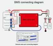
heres a picture of the diagram, when you connect all the balance connectors wires check it again. Its rare for a bms to come from the store bad. It happens but its rare. One time I had a bms where the wiring diagram was very confusing I gave up trying to wire it. But the one you have is fairly simple, the hard part is not connecting the balance wires in the wrong cell.
The bms won't work if one of the balance wires is loose or connected in wrong place. Also if everything is connected right but one cell voltage is too high (over 4.20) or too low (under 2.8 volts) the bms wont work, thats another thing to check.

One thing I notice about this particular bms is that it comes in two types, one is "same port" and the other is "2 port", you might want to doublecheck you have the right one.

To add pictures just press attachments on the post reply and then press add files ( browse to your picture and choose it) then press place inline. Make sure picture is jpeg and small size 100 kb or less so it loads fast.


a bms1.jpg
 
john61ct said:
And I don't know why you keep saying "group", in balancing each cell needs to be treated individually.

For real? By what mechanism do you think cells placed in parallel to each other could become imbalanced from each other?

When cells are paralleled together to multiply their Ah capacity, they behave as a single cell. There's no individual variation to address.
 
jonyjoe303 said:
One thing I notice about this particular bms is that it comes in two types, one is "same port" and the other is "2 port", you might want to doublecheck you have the right one.
Are you aware of the functional differences between the two types?

Could you link to BMSs you consider quality, reliable for **protective** functions?

Ideally adjustable setpoints, and a range of ampacity choices from one vendor's model line.

BT would be nice but not essential.

 
Chalo said:
For real? By what mechanism do you think cells placed in parallel to each other could become imbalanced from each other?

When cells are paralleled together to multiply their Ah capacity, they behave as a single cell. There's no individual variation to address.
Those statements are true in theory, under ideal conditions.

I have seen many paralleled blocks with unevenly worn cells, where while under high-C use they differ by a lot in their response, to the point of being dangerous.

Of course if they are allowed to rest in parallel they will self-balance, but that process can take a very long time.

In those circumstances, access to individual cells is critical as a diagnostic, to identify those needing earlier replacement.

Some well-funded owners may only buy new cells, all commission-tested as matching, and replace the bank as a whole when capacity (SoH) starts to degrade.

But many can't afford that, buy salvaged cells for cheap, and need the bank infrastructure to compensate for their use of poorer quality and unmatched cells.

 
Welp, I got it up and running. I replaced the orange cells (they were hovering at around 1Ah) with some broken in 30Qs once I was convinced the BMS was working properly. I also fixed my Arduino spot welder so im no longer forced to weld at the maximum setting. This was very informative.

Thanks everyone!
 
The below is mostly a late reply, but is being posted to correct misinformation in the thread, and to help the OP understand some things (and avoid making assumptions about things they can only partly see, so they don't get misled in the future).

SwampDonkey said:
I was talking about the photo halfway down the page. Shows them testing one in a bowl of water. with a positive lead on the P- wire.
No, it shows a RED wire on there.

Color is irrelevant, since you can't see the actual connection it goes to, you don't know if it is going to a positive, negative, or something else.

FWIW, the picture doesn't even show you something under test, it just shows something wired up to a box with speaker wire connectors, a pair of wires that someone is holding in their hands, and the BMS sitting in a bowl of water with test equipment/etc. nearby. It does not show any test of the device at all, other than that the device is heavier than water.


john61ct said:
Those statements are true in theory, under ideal conditions.

I have seen many paralleled blocks with unevenly worn cells, where while under high-C use they differ by a lot in their response, to the point of being dangerous.
"Ideal conditions" do not need to exist for ohm's law to operate.

Unless you have very high resistance connections between the cells in a group, *and* the series interconnect is not evenly distributed between the cells in a group, then there will be no difference in voltage between them, regardless of load. (A load high enough to cause such a difference to be visible would cause heating in the interconnects and cells, as well, and that heat could be very high if the interconnect resistances are really that high. Potentially high enough to cause a fire--the imbalances are not the issue at that point, the connections are--and the connections may well be the *cause* of the imbalances!).


Unless the pack is very badly built, balance does not need to be performed on individual cells.

If individual cells do not remain in balance in a parallel group, at least when the pack is built, then the cells are defective and should all be replaced with new cells anyway.

If you measure different voltages on cells when they are not under load, they are not connected in parallel. (or the resistance is so high, they are effectively disconnected).

Anyone measuring different voltages on cells in the same parallel group must fix this problem to make the pack usable. They should probably start by first disassembling the whole pack, and testing each of the cells to ensure they are all good, and of equal capability, and then rebuilding the pack to correct the problems with the interconnects causing them to be effectively disconnected from each other. If they do not wish to disassemble and test the cells, they will still need to rebuild the pack to correct the interconnect problems (which generally will require disassembly anyway, which is why I recommend it).


In those circumstances, access to individual cells is critical as a diagnostic, to identify those needing earlier replacement.
This *is* true, when diagnosing a defective pack.


But many can't afford that, buy salvaged cells for cheap, and need the bank infrastructure to compensate for their use of poorer quality and unmatched cells.

True...but it doesn't negate that a correctly built parallel group will have such a low resistance between paralleled cells that there will be no voltage difference between the cells in that parallel group.


john61ct said:
Chalo said:
The sense wires are not for charging! They are for measuring voltage and draining small currents (tens of mA) from the highest voltage cells to bring those into balance with the others.
Depends on the charger.

Lots switch over to use the balance leads for charging soon as the first cell hits the setpoint.

Some charge only through the balance wires, bo bulk pack-level charging at all.

"Sense wires" are usually used for 4-wire chargers.
No.

You are posting about at least three completely different things.

In a common BMS, no charging is performed by any of these balance wires.

They are ONLY for sensing the voltage of the parallel cell group,

In some cases they are also used for draining off excess charge (in a resistive BMS).

In very few cases they are used for transferring charge, in the rare capacitive BMS; almost none of the ones commonly seen do this.


A charger that charges thru balance wires has nothing to do with this thread, because that kind of charger does not use a BMS on the pack. (you could use one on a BMS'd pack if you disconnect the BMS, but that is not what is being discussed here.)


Additionally, a charger that uses a four-wire method (sense wires, plus charge wires) is pretty much never going to be found on a DIY ebike/etc type pack or charger, and it isn't going to be on a cheap BMS for such a pack. These are mostly going to be found in labs for accurate testing, and potentially in large commercial packs of some type.

All you are doing is confusing the OP with things like this.
 
Yes, in this case the BMS works like most of this type.

fechter said:
The balancing function turns on a resistor across any cell that reaches the balance threshold voltage (generally around 4.2v). When the resistor turns on, it slowly drains that cell to bring it down to below 4.2v. If the bleeder resistor can't keep up, the cell voltage will keep going up until it reaches the OVP voltage and turns off the charge current. If this happens, the charge stops until the cells are discharged down to the "release" point and charge can resume. The balance wires can't supply any charge current with most boards, only drain a high cell.

The actual trigger and balance voltages vary somewhat with different boards but should be listed in the specifications.

I avoid doing balancing this way myself, prefer distributing BMS functionality across separate devices and having more than one layer of protection for the key cutoffs.

I was responding to the general statement that the balance wiring is never used for charging, and not being familiar with that specific hardware. . .

But I agree getting into the weeds on discussion of such details is distracting, my apologies.


Back
Top