Liberty Trike controller upgrade

icrude

100 mW
Joined
Aug 19, 2023
Messages
36
Location
Mission Viejo
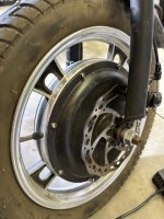
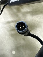
Hey everyone, so I have the libertytrike, and we are trying to change the controller to go from 36v to 48v because this thing is limited to 12mph. I’ve attached some photos of the original setup and motor connector. I got a new controller (link attached) and have the three main wires hooked up for the motor (green yellow blue) but the motor doesn’t want to work. We aren’t completely sure how to wire the throttle up. It has red, black, green, blue, and yellow but the new controller only has black white and red for throttle. The original blue and yellow we think is for the reverse which we don’t need those. So we tried red to red, black to black, and green to white. The motor does seem to be getting power because it locks up when we twist the throttle. So I’m not sure if there is something obvious we’re missing. We didn’t wire up the hall wires (does that matter). Any ideas would be appreciated.


Attachments

  • 71407002380__A4C409DC-1D7A-4F01-B0D9-4EF420A60F19.jpeg
    71407002380__A4C409DC-1D7A-4F01-B0D9-4EF420A60F19.jpeg
    116.3 KB · Views: 4
  • 71407003470__7503990C-A165-41B6-89BC-5439202DE351.jpeg
    71407003470__7503990C-A165-41B6-89BC-5439202DE351.jpeg
    75.8 KB · Views: 6
I’m sorry, I’m not trying to ask the same question….I guess what I don’t understand is while the bms may have been tripped this time, a few weeks ago with my stock 20amp controller the same thing happened. Would the bms be tripped on this 30amp bms battery on a controller that’s only rated for 20 amps? (And if I asked the same thing again I’m very sorry)
The battery BMS can provide several layers of protection, depending on the BMS unit used. Typically they provide over discharge protection and can also provide low voltage protection. As others have stated, this could be a voltage sag issue, tripping the BMS (Chalo is correct that it's likely not tripping based on overcurrent). Even if the battery appears to be fully or close to fully charged, all it takes is a few bad cells in one or more of the groups that can cause the battery voltage to sag enough to trip it. At rest, the voltage may still appear fine after it's sat for a little while. This is why knowing what the voltage is doing when the problem occurs (or even during your normal riding) is an important data point for diagnosing the issue.
 
The battery BMS can provide several layers of protection, depending on the BMS unit used. Typically they provide over discharge protection and can also provide low voltage protection. As others have stated, this could be a voltage sag issue, tripping the BMS (Chalo is correct that it's likely not tripping based on overcurrent). Even if the battery appears to be fully or close to fully charged, all it takes is a few bad cells in one or more of the groups that can cause the battery voltage to sag enough to trip it. At rest, the voltage may still appear fine after it's sat for a little while. This is why knowing what the voltage is doing when the problem occurs (or even during your normal riding) is an important data point for diagnosing the issue.
Ok so I’ll hook up a voltage meter and ride it till she dies and check it the second it dies.
 
You don't need to ride until it dies, although that would be a good test. Even just riding up a big hill and seeing how much the voltage sags compared to flat ground would provide good info.

Again what’s strange is it died under like quarter throttle on a flat road. Never died on a hill.
 
You don't need to ride until it dies, although that would be a good test. Even just riding up a big hill and seeing how much the voltage sags compared to flat ground would provide good info.
They arent looking for that as an answer, they want a device to help them. Maybe a cell phone app or a display screen, another screen bro.
 
So I have a trike that has the 6 hall sensor wires (plus the 3 main motor wires). I already purchased this controller (which I can return but wanted to double check first) and on the Amazon page it said “no for hall motor” in poorly written English. I’m assuming that means it won’t work for motors that have the 6 hall wires? It does have the right 3 bigger motor wires, and another white connector that looks like it’s for the 6 hall wires (and it’s even labeled for the motor) but it only has 5 wires. Could this be used for the hall wires and maybe just missing one?


My mid-drive motor is the opposite; only has 5 hall wires, hooks up to controllers with 6 wires and works. Some cut-out issues once in a while (that are probably unrelated) but otherwise smooth. I would still buy a new controller though (try to get a controller/display pair).
 
Be careful riding that thing faster than 12 mph. Heck, be careful riding it at 12 mph. It's only 24 inches wide with high seating, so it's a tipover waiting to happen. And unlike some other mobility scooters, it isn't ballasted low in the base with lead bricks. A good followup retrofit would be to add a wider rear axle to stabilize it at speed.
12mph is ok for this 79er. Now nearing 6,350 miles over 4 1/2 years. 15mph is fast enuf coasting down a hill.

Top speed of 20mph is too fast, but more 13s power would be nice for hill climbing. Wish top speed was at least 15mph, ... that way can still cruise 10-12mph at only 2 bars.

Wish the current Controller could handle at least 11S or even 12S. Having accomplished enuf useful mods already so accept 8-10mph at 2-3 bars. Only charge 90% (41.0v).
 
How can one determine if the LT 36v Controller can handle 12s without damaging it? It's a pretty substantial looking Controller. Would like a little more power for hills and 14mph speed. Controller is 20amp so peak power difference of 820w (10s) versus 985w (12s). Is that enuf of an advantage even if current LT Controller could easily handle 12s without overheating?

Will open up and take photo if that will help someone determine Controller voltage limit. Maybe 13s is even a possibility without overheating the LT Controller, but prefer 12s with existing LT Controller.
 
Be careful riding that thing faster than 12 mph. Heck, be careful riding it at 12 mph. It's only 24 inches wide with high seating, so it's a tipover waiting to happen. And unlike some other mobility scooters, it isn't ballasted low in the base with lead bricks. A good followup retrofit would be to add a wider rear axle to stabilize it at speed.
I was wondering if there was a way to expand the axles... Is this go to the machinist? or is there like a kit?
 
I was wondering if there was a way to expand the axles... Is this go to the machinist? or is there like a kit?
For the Liberty trike? Or for something else?

Any other trike axle the same diameter as the Liberty's is likely to be wider. So using one of those would widen the trike's track.
 
I bought this controller hoping it would work with my e-bike. It does but randomly the motor will just cut out and not work. I didn’t hook up the hall wires which I’m thinking may be why. I see that in the photo it has hall wires but it says in the description “no for hall motors”. Why would it have those hall wires if it’s not meant for hall motors?

 
The video states it can drive “sinusoid motor, rectangula motor, no for hall motor”

To me, that describes sine wave (needs halls), square wave, and sensorless, so a dual mode controller. I’d check the phase wire connections or all of the connectors if you’re have an intermittent issue.

Note that controllers don’t have hall sensors, the sensors are located in the motor.
 
Thank you for the reply. Just so I better understand this stuff, why don’t I need to install the hall wires for this to all work? I only installed the three phase wires and it works. I thought hall wires are needed for it all to work. I am installing this on a libertytrike btw if you know what motor that has.
 
The controller will operate either with or without hall sensors connected to it.

If you don’t plug them in it won’t receive any hall signals from the motor and will automatically run in sensorless mode.

If you plug them in it will receive hall signals from the motor and automatically run in sensored mode.
 
And how would running in either mode benefit a beginner like me?
Hall sensors allow for smooth starts from a dead stop. Sensorless can be rough starting, since the controller is initially trying guess the position of the stator, sort of randomly, so it will start spinning and in the right direction. They can be noisy at start as well. With hall sensors, and with a sine wave controller, the motor will be quiet and start smoothly. Having the sensorless mode available is nice in case the halls fail, but I'd always opt for starting out with halls (with the comfort of knowing the bike will still go if the halls get damaged).

Some controllers can start in sensored mode for a smooth start, and run sensorless once it's moving. Sensorless does have advantages at higher RPMs, so those controller take advantage of both modes.
 
Last edited:
Thank you so much for the replies. This may be a long shot to ask but are you guys able to determine if this controller would work with my stock lcd display and on/off switch? The switch gets routed thru the display and the display connects to the stock controller through a 5 pin green connector.
 
Thank you so much for the replies. This may be a long shot to ask but are you guys able to determine if this controller would work with my stock lcd display and on/off switch? The switch gets routed thru the display and the display connects to the stock controller through a 5 pin green connector.
Unlikely. Displays are manufacturer specific and sometimes controller specific. From the description, I doubt is supports a display, but looking at the items under "Frequently bought together" include throttles with on/off and voltage readout functions. If they work with the controller, then there should be a connector labeled something like Electric Key Lock/Key Switch/Electric Door Lock/Ignition/Power Lock. That connector is used with a switch to apply battery level voltage to in order to turn on the controller. So, those throttle/switch/voltage readout functions will use the two additional conductors (for the examples listed on Amazon) to perform the on/off function as well as the voltage readout. The three wire connector is used for the throttle input/output. You may be able to reuse your switch to turn the controller on and off, if you decide not to go with a combo throttle unit.
 
I moved all the posts and threads for this into the original thread about it, since it's all for the same controller, etc., to keep all the info together for you and those helping you.

If you haven't already done so, I recommend drawing yourself up a wiring diagram of the original controller wiring that worked, then the new controller wiring that worked, and then the wiring that you have now (which is presumably different than you had wired up before).

Then you can see the differences between them to figure out what (if anything) is incorrect now vs what worked before.

If you don't see any differences, then you could post your diagrams here, and we can look at them to try to see what's different / incorrect, and perhaps guess if any of the possibly incorrect wiring has damaged anything on the trike or the controller.
 
Got it! There was a wire before that said “must be connected” which I didn’t think I used before but I must have. I plugged that into the positive terminal and it works perfectly. Thanks everyone!
 
One last thing, I was reading the description on Amazon for the controller and it does come with the hall wires (but the description also says “no hall” which is confusing. Can I try hooking up the hall wires if it will help?
 
Back
Top