Minimising rotor losses

ElectricGod said:
madin88 said:
@ ElectricGod

you mentioned non of the motors you posted pics from have electrically insulated magnets.
Couldn't it be that the magents have some kind of transparent coating for electrical insulation?
Have you measured the resistance between two magnets or what gives you this idea?

You should go back and read what I wrote. Everything you asked was addressed already.

No.
Let me write it up once more.
Above the rotor pictures you put a text with something like "magnets glued down to bare metal"
The question is:
do the magnets have a non-conductive (transparent) coating, or is it nickel coating or some other surface treatment that is electrically conductive.
I have seen magents with non-conductive coating in some chinese (geared) hub motors thats why i am asking :wink:

Is it so hard to answer this question?

ElectricGod said:
A quick discussion on this eddy current loss issue. It seems that lots of little magnets is better than a few large ones for controlling this issue. Of course that means you have a motor with 200 poles to eliminate the eddy currents. Clearly there has to be a middle ground between ridiculous magnet counts and minimizing eddy losses. I think this may be the reason why hubs and outrunners have lots of magnets. This may be the place where eddy current losses are the worst so use lots of magnets. While in an inrunner, it's negligible so much fewer magnets is viable.

The pole count stays the same.
larsb has already mentioned, but it seems you did not understand
See here: LINK

ElectricGod said:
To me this underlined section says that you want minimum electrical resistance between the magnets. Perhaps the problem with your motor is the exact opposite of what you think it is? Perhaps most of the magnets do NOT conduct electrically with the back iron? This is also consistent with what is observed in all of my inrunners and outrunners. AKA no insulating elements between the magnets to maximize electrical conductivity. If this is true as I interpret it, try soldering a copper loop across the tops and bottoms of your magnets to make them all electrically the same. Solder flows to chrome quite nicely. Pretin all solder locations. If you use a hot soldering iron and are quick, you won't heat up the magnet excessively before the solder flows and bonds the copper to the chrome. I bet an 18 awg strand is all that's needed top and bottom. Worst case, it doesn't work and you unsolder the wires.

IF I see lots of losses (hot magnets due to eddy losses under no load), I can do this to my motor too.

I never have soldered on magnets :lol: so i don't know how and if this can be done, but try it out and compare the no-load losses!
 
Every motor I've opened had the magnets glued using some kind of epoxy, which quite likely provides significant electrical isolation from the back iron. I'm not sure the eddy currents of the rotor are being made a big deal on outrunners. Aren't those losses pretty minimal in relation to total iron losses?
 
ElectricGod said:
Furthermore, I just posted what my friend in the UK has told me several times. That electrical conductivity is not the issue.

He just told me that NOT having gaps between the magnets is creating the heating and losses in the magnets in higher RPM motors. Which I just posted here earlier today.

He may well think that but I'm afraid he's wrong. Or, at least, it's misleading to say that.

Obviously, there will be a reduction in eddy currents as you reduce the magnet area but you shouldn't be designing your motor around that..

The specific slot/pole combination and the rotor speed are the most significant contributing factors to rotor losses. Segmenting the magnets reduces eddy currents but the segments need to be electrically isolated for maximum benefit.
 
ElectricGod said:
I haven't actually checked as I've already posted several times. I LOOK at my pictures at the magnets and they look like bare chrome on bare iron backing. ALL of my inrunners and that IPM armature I posted have full metal on metal contact between the magnets and back iron. That means there is a virtually 100% chance they are electrically conducting with each other.
Aha!, but your eyes will not tell you if the coating is electrically conductive or not :wink:
It could be measured quite easy with a DMM by just holding the tips on two mangets, is that to much to ask for?
Besides, this is a review of the RV series motors, not a debate about motor design aspects.
I appreciate your effort and time you put into your thread here with all the photos, but i have a hard time to understand that someone who mentioned manytimes that he is no motor expert and that this subject is 100% new territory for him, generally makes such comparison.

We are all here to learn and share what we already know, but those texts full of pseudo-knowledge (especially the first post) doesn't help anybody.
 
EG, to assert that electrical conduction is not a prerequisite for eddy currents to exist is hard to comprehend. If you understand how an eddy current brake works you will understand that electrical conductivity is an absolute requirement. If you stumble upon a well designed motor you will find not only that the rotor magnets are epoxy coated but also magnet coverage is not 100%. You won't find nickel plated 100% coverage magnets in a YASA, Heinzmann, Emrax, or a Porsche 918 Spyder electric motor.
 
ElectricGod said:
Miles and larsb seem to think that no electrical conduction between magnets is best. I flat out don't know. The motors I've checked myself and the one that Madin checked show conduction. BUT Madin found a magnet in his motor that was electrically isolated and the rest were not. What's the correct answer?
As mentioned i think when they installed that magnet the glue was already viscously, or they just used much more glue which led to a tiny gap and electrical insulation to the back iron (and the rest of the magnets).
I couldn't tell you and so far, my freind in the UK says it doesn't matter and at least 2 people on here claim you don't want electrical conductivity. Furthermore, as far as I can tell, it LOOKS like ALL of my motors probably do have electrical conduction between the magnets and the back iron and with each other.

Go look at my post early on where I show lots of armatures. Do any of them look like there is isolation between magnets? It sure sdoensn't look like there is to me.
As mentioned from the look you cannot find out if the resistance between magnet and back iron is 100000Ohm, 10Ohm or 10mOhm.
One thing is clear:
For lowering eddy current losses in stator and rotor, electrical insulation is essential!
At least as far as the so called "magnetic penetration depth" goes into the material.
This is why good motors have very thin stator steel laminations and segmented magnets with non-conductive coating, and it makes a huge difference if the resistance in the eddy current path is 15mOhm or 15Ohm. I = U / R ohms law so latter would mean 1000 times less eddy current!

When it comes to IPM motors the losses in the magnets are pretty much negligible because they are usually placed further away from the air gap, while on motors with surface mount magnets the losses in the magnets alone can make a large part of the total no-load losses.

Well, we are talking here about a <3kg 150USD motor, so no wonder you won't find top-notch engineering on this one, but than also don't expect to much
>>
7. The C80100 is rated for 7kw which is silly. 80mm stators typically max out at 5kw. My C80100 does a bit less than that. The RV-100 is rated for 2kw continuous and 5kw peak. Bigger magnets, bigger stator, 100% full stator windings...I bet 6500 watts continuous is likely.

I bet it will be hard to even get out the 2kW continuous as it was specified as those motors are usually overrated :wink:
But you'll see once you have it running on the vehicle. So far you only speak from pictures.
 
I have read a few papers on the subject and they echo the advice Miles gave. Non conductive magnet coatings and segmentation reduces eddy current losses in the magnets but there are no epic gains to be had, if I recall correctly we are talking about a few percent improvement in overall efficiency. The downside is increased cost of manufacture so for a typical cheap and cheerful china motor it just isn't worth the effort or expense.
 
I guess you didn't really read the paper i linked.

The 4% increase of efficiency they got in that study was from slotting magnets AND backiron ring.

What does it tell you?

Should be that both the magnets and backiron had eddy losses that could be improved by lowering conductivity.

I also have read papers where they tried segmenting magnets both in circumference and radially.

Circumferential segments were best but improvements were seen for both types.

What does it tell you..?

BUT you seem so aggravated that the earth might just as well be flat - you cannot see it's round, it's actually flat where you stand so where's the proof?

Come on, it's time to relax this discussion. The halls should have arrived soon, before that you can try the motor with a sensorless controller. It should tell you what the noload current is roughly.

If you later get a lot higher current with a sensored controller then you know the hall setting or combination is off. If you get a lower noload current with the sensored controller then you know you got it right.
 
It is here:
larsb said:
Link to full paper:
https://scholar.sun.ac.za/bitstream/handle/10019.1/45192/wills_reducing_2010.pdf?sequence=2&isAllowed=y

The magnet and backiron segmentation in this paper makes a 4% efficiency increase. If a motor can disperse 2000w heat at 85% efficiency then this would mean you can increase continuous output from 13kW to 18 kW with this improvement. :D

I think you just might kill your motor with the copper wire test if you run it too long at a decent amperage. Or during the soldering.

I did a ten minute search and found this. There's a lot of info out there if you want to find it.

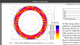
image.png
image.png
image.png

I'm surfing on my phone so you have to actually read the sections i clipped, i won't highlight it.

It's to show
-that the model for this simulation is containing insulated magnets
-that the penetration depth for eddy currents can be large
-that the purpose of segmentation is insulation (or actually for increasing of resistance in the eddy current path by creating smaller domains)
 
ElectricGod said:
My comments and conclusions from this article:
"Reducing PM Eddy Current Rotor Losses by Partial Magnet and Rotor Yoke Segmentation"

Regarding magnet segmentation right up front this article says this which basically maens magnet segmentation is not ever going to be something any manufacturer will likely do.

"In order to reduce the losses caused by eddy currents in the magnets and rotor yoke of a PM electric machine, a number of effective methods can be used. One method that imposes the least restrictions on machine performance is segmentation, which can be difficult to
implement as magnets need to be cut, insulated and re-glued, which is a laborious and costly process."

Except it is. Look at the link below inside an Emrax motor for an implementation of the YASA design. See the segmented magnets?

http://build-its-inprogress.blogspot.com/2017/05/emrax-motor-teardown.html
 
Back
Top