Minimising rotor losses

deleted
 
deleted

---

@ ElectricGod

All the discussion started because you were saying you paln to remove the magnets, grind off 1mm from one sides and glue them in with JB weld, but someone mentioned you should not use JB weld because it is electrically conductive... I think this is a stupid idea, but do whatever you like!

My idea was, instead of grinding on the magnets and glue them back in, to buy new magnets and you could replace each single magnet with 3 or 4 smaller ones to improve things even further.
As for the RV100 this would probabaly lead to much lower heat in the rotor and also more torque.
More torque because by having 4 small rectangular (non bended) magnets instead of one large, the gap to the back iron would be much smaller and so the flux return over the back iron would be improved -> more flux density = more torque (at least peak torque or when it's close to saturation).
 
ElectricGod said:
These are my comments and conclusions based on the "Rotor Eddy-Current Loss in Permanent-Magnet Brushless AC Machines" article.

...
"However, for high frequency harmonics or when a metallic retaining sleeve with high electric conductivity is used, the skin depth becomes small and the resistance limited assumption may not be valid."

A "metallic retaining sleeve" implies an outrunner or hub motor in my mind. in the previous paragragh is this:

"They are based on the assumption that the magnets are surface-mounted and the eddy currents are resistance limited, i.e., the relatively high resistivity and low permeability of permanent magnets will limit the amplitude of induced eddy currents and the reaction field produced by the eddy currents is negligible,"

I'm not sure about the "resistance limited" or "high resistivity" statements. Are they references to electrical resistance or something else? I have a "peeled neo". It wouldn't be hard to check the resistance of the magnetic material. IF this is a reference to the electrical conductivity of the magnet, then the WORST possible coating for them would be chrome! Chrome would magnify the amplitude of the eddy currents. IF this is a reference to some characteristic of magnets that is NOT electrical resistance then right away in the introduction, this article says that electrical conductivity and its effects on eddy currents "is negligible" and "may not be valid". I'll keep reading, but that's my conclusions so far.


"To reduce rotor eddy current loss, each pole of magnets is segmented into four pieces."

"As will be seen from Fig. 4, the stator current excitation produces a 2-pole rotating magnetic field which can penetrate deeply into the rotor magnets, resulting in significant eddy-current loss if the magnets are not segmented. As the number of segments per pole increases, the eddy-current loss decreases. However for the machine under consideration, the rate of reduction in eddy-current loss diminishes as the number of segments is greater than 4."

"It has been shown that forward and backward rotating space harmonics of different orders may result in the same frequency seen by the rotor. Therefore, when more than two segments per pole are employed in PM machines, the loss in each segment may be significantly different. Such nonuniform distribution of eddy-current loss will inevitably give rise to uneven temperature distribution and increases the
risk of partial irreversible demagnetization."


Clearly segments of magnets reduce eddy current losses. It is also stated several times that not all segments of magnets that make up any pole will have the same losses. One segment will probably have much higher losses than the others which means that one magnet segment gets much hotter than the others. I don't honestly know why they bothered with segmented magnets. It's not practical for a manufacturer to do this and the fact that magnets in the same pole won't have the same loses means lots of new issues. Why bother at all? The implications, complications and caveats are possibly worse than having single segment magnets like any motor I've ever seen has. IMHO segmented magnets sounds like it's just not worth the trouble. I suppose since this study is about reducing eddy currents, then it's applicable to the study, but in the practical real world, fairly pointless.

In conclusion, from this article, I see no where that they state that electrical conductivity between the magnets and the armature back iron is relevant.

i read some 20 papers today, all on rotor eddy losses. But i still had time for a swim and hiking a small mountain :D
- Regarding metallic retaining ring: it's most likely a retaining ring on the outside of the magnet core on inrunners that keep the magnets from bursting in higher speed applications. the retaining ring material properties give a low skin depth so that the eddy currents do not penetrate beyond the ring. Just check the formula for skin depth and you'll see the base for this.
Skärmavbild 2018-07-27 kl. 00.04.34.png

- The other section regarding resistivity and permeability of magnets are also regarding if the eddy currents are limited by resistance or inductance. The only paper i've found where the induction limited model was used was in high speed application - that was 50 000 rpm.
It is the limiting factor at much higher frequencies than the sub 500hz that's in this motor.

- That the reaction field of the eddy current is negligible is not the same as the losses are, it means it does not affect the results!
That whole paper is dealing with resistive losses, nothing else since they excluded it as not limiting.

Please read this sentence from one of the papers:
Skärmavbild 2018-07-26 kl. 22.27.48.png
Skärmavbild 2018-07-27 kl. 00.10.09.png
or this sentence from previously linked paper:
Skärmavbild 2018-07-26 kl. 22.34.26.png
Do you see the word insulated.. and what i mean?

- The reason for them pointing out that the magnet segments have different losses is that most other publications assume same losses in all segments and base the motor design on this. The losses and temperature increases are still lower than the non segmented magnets even in the high loss segments but the high ones need to be considered as the limiting factor in the motor design. See here:

It is concluded before this table that the previous made modelling by other authors is giving a correct average for the segments of a pole but that individual segments have differing losses. Average here is roughly 15w per segment (58/4) and the high loss segments are at 18w so losses are still improved when compared to non-segmented magnets.

etc.
 
Lol I spent like four hours reading and writing this post, so hopefully we can get this useful conversation moved to its own topic.

I have read all the posts and links in this thread, and I think we all agree on a lot of things and disagree on just one thing.

Agreements
  1. Different motors have different designs and optimizations that affect rotor eddy current losses and the features included to minimize them.
  2. Some motors have high rotor eddy current losses while others do not. From larsb's article, "a high proportion of eddy currents in the rotor are induced by asynchronously rotating stator MMF harmonics." We know that synchronous motors have large synchronously rotating stator MMFs to make them rotate. It seems that some synchronous motors also have "asynchronously rotating...MMFs" that cause significant rotor eddy currents.
  3. This is why some "nice" motors have segmented magnets (Emrax) and some "nice" motors do not (Motenergy is a bad example - it is just a big motor, most Joby motors I have seen pictures of are "nice" and do not have segmented magnets).
  4. Lower cost optimized motors will probably not have segmented magnets, but sometimes we might wish they had them due to their high rotor eddy current losses (larb's Revolt motor).
  5. Gaps between different magnet poles can reduce rotor mass and rotor eddy current losses.
  6. Segmenting individual magnet poles can reduce rotor eddy current losses.
  7. Segmentation involves axially isolating the magnets from each other.
  8. Electrically isolating different magnet poles from each other is unnecessary.

Disagreements
ElectricGod said:
Electrical conductivity between the magnets or between the magnets and the back iron in the armature is irrelevant.
I think the first part "...between the magnets..." refers to between magnet poles which we agree on above.
The second part "...between the magnets and the back iron..." is where the disagreement is. I am not 100% sure, but I think that isolating magnets from the back iron is not necessary. It is like how stator laminations are shorted to each other where they connect to the hub or shell that holds them together.
I do not think that madin88's comparison of not isolating vs isolating magnets to SSPMS vs DSPMS is quite accurate. The purpose of segmentations/laminations is to intersect/block the induced currents from the moving magnetic field. The magnetic field decreases in strength as you move away from the stator/into the rotor. The first thing you reach is the magnets. Segmenting the half of the magnet closest to the stator ala SSPMS decreases rotor eddy current losses in the first half of the magnet as seen in the figure below.
sspms.PNG
As we move deeper into the magnet past the segmentations, rotor eddy current losses increase back to normal since we are no longer segmented and nothing exists to intersect our eddy currents.
However, if we segment the second half of the magnet (the half that is further from the stator) ala DSPMS, we significantly decrease rotor eddy current losses in the second half of the magnet while losses in the first half of the magnet only decrease marginally from SSPMS.
View attachment 2
pms.PNG
Note in the figure above that the segments from the first half are "shorted" by the segments from the second half since the incisions are not aligned with each other. Despite this "shorting," the DSPMS method is almost as good as the FMS method as can be seen in the plot below.

Finally we get to the back iron. Since the back iron is highly magnetically permeable, the moving stator magnetic field we have been following does not penetrate very deeply. We can thus get good results with "partial rotor yoke segmentation."

Comments welcome.

(larsb's article referenced above linked here: https://scholar.sun.ac.za/bitstream...ills_reducing_2010.pdf?sequence=2&isAllowed=y)
 
I think the summary made above by user "thepronghorn" is correct - thanks for the effort!

I can see the logic in chopping and moving the good stuff to another thread, then we can keep some good references without the arguing and EG can keep on with his motor review.
 
thepronghorn said:
Lol I spent like four hours reading and writing this post, so hopefully we can get this useful conversation moved to its own topic.

I can imagine that it took plenty of time to read through the papers and write that damn good summary.
Thank you. A moderator should create a new start post and put your text there.
[*]This is why some "nice" motors have segmented magnets (Emrax) and some "nice" motors do not (Motenergy is a bad example - it is just a big motor, most Joby motors I have seen pictures of are "nice" and do not have segmented magnets).
Actually the Joby motors do have two (2) pcs fully segmented magnets (FMS) per pole :)
If we look at the graph from the paper, this already would have lead to only 1/5 of magnet losses on the test machine from there


But as we learned it depends alot on the the motor design and on a different motor things will be different.
It seems that slot and pole count play a big role how large the improvement could be when segmenting the magents.
regarding this paper:
http://eprints.whiterose.ac.uk/826/1/wangjb8.pdf
I do not think that madin88's comparison of not isolating vs isolating magnets to SSPMS vs DSPMS is quite accurate. The purpose of segmentations/laminations is to intersect/block the induced currents from the moving magnetic field. The magnetic field decreases in strength as you move away from the stator/into the rotor. The first thing you reach is the magnets. Segmenting the half of the magnet closest to the stator ala SSPMS decreases rotor eddy current losses in the first half of the magnet as seen in the figure below.

.....

Comments welcome.

(larsb's article referenced above linked here: https://scholar.sun.ac.za/bitstream...ills_reducing_2010.pdf?sequence=2&isAllowed=y)

Yes it wasn't written explicit in any of those reserach papers that insulation between magnets and back iron is important, but if you look at what DSPMS does, installing such a magnet to steel without insulation would again electrically connect the segmented areas and short them out.
I don't know how much this would worsen things if doing so, but it cannot be good, right?

The Emrax has epoxy coated magnet segments which are glued to a laminated back iron yoke.
If those magnets would not have isulating coating, they would short out all the lams behind it, right?
It was mentioned that conductivity of Neodym magnets is much worse as from steel, but regardless there would be more eddy currents if the coating would be conductive.
The back iron lowers the elctrical resistance of the magnet and at the same time the magnet lowers the elctrical resistance of the back iron, therefore it makes things worse.

Here is a picture of the rotor of my Neu 8057:

FmcowP.jpg


It looks like there is no coating on the magnets (raw), and the DMM shows 0Ohm (beeps) between magnets and back iron.
When spinning at 5000-6000RPM, the temperature of the rotor climbs from 20°C to 45-50°C in a very short time and than it stays there.
As i have a second rotor lying around, i plan to do full magnet segmetation py replacing one magnet with 3 or 4 pcs (would like to use 4pcs but it depends on the price). I also have seen that segmented magnets could improve torque and field weakening capabilities :)

Yesterday i have asked a magnet manufacturer from china for a quotation (it will be N45H grade with epoxy coating).
 
Speaking about segmented magnets and that most manufacturers don't use them: the QS 3000W mid drive motor has segmented magnets.

5 pole pairs, 40 magnets total equals 4 magnets per pole.
image.jpeg

Efficiency 89% with drive losses included according to QS. That's sweet if it's correct!
 
thepronghorn said:
As we move deeper into the magnet past the segmentations, rotor eddy current losses increase back to normal since we are no longer segmented and nothing exists to intersect our eddy currents.
However, if we segment the second half of the magnet (the half that is further from the stator) ala DSPMS, we significantly decrease rotor eddy current losses in the second half of the magnet while losses in the first half of the magnet only decrease marginally from SSPMS.

Between SSPMS and DSPMS (pic Fig. 7 and Fig. 9) the magnet loss density decreases from about 0,25 to 0,16 for two segments, and from 0,1 to 0,08 for three segments already on the magnet face, even though both kind of mangets have same number of segmentations on the side facing the stator (pic Fig. 3).
I would say this shows the influence of electrical conduction between the segmented areas and material which is further away from the stator.

larsb said:
Speaking about segmented magnets and that most manufacturers don't use them: the QS 3000W mid drive motor has segmented magnets.

5 pole pairs, 40 magnets total equals 4 magnets per pole.

Efficiency 89% with drive losses included according to QS. That's sweet if it's correct!
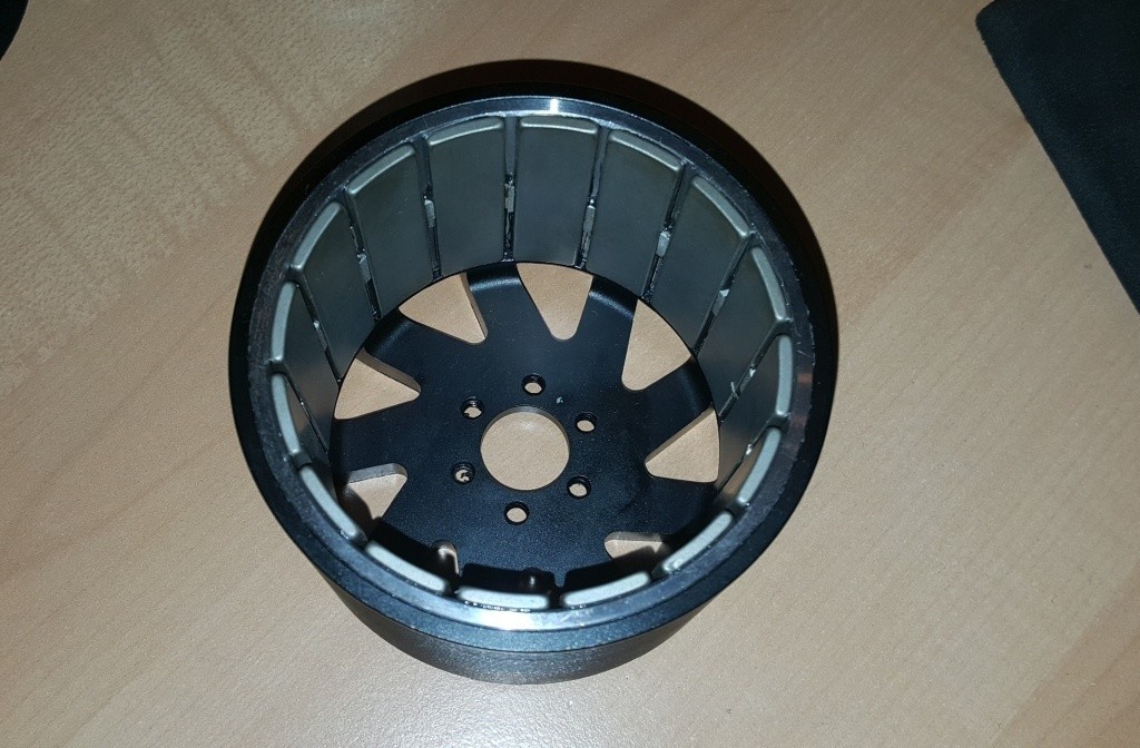
Yup that looks like a very well designed motor.
It has an IPM rotor so there are almost no eddy losses in the magnets itself as they are placed further away from the airgap. But than there will be higher rotor core losses, but the core is made of steel laminations so everything is fine :)
There is also a "2000W" version of this motor which has same design.
 
Sorry folks...just wanted out of this thread and conversation so I zeroed out my posts.

I learned a lot about eddy current losses and that was cool.

Enjoy this without me. I'm glad my motor review thread is no longer getting hijacked.
 
This paper is interesting: higher conductivity is better in the retaining sleeve of topology 4; a 12-slot, high speed motor. It's 240 000 rpm, so not really like an ebike motor :D

The overlapping winding used cancels some of the harmonic content, still with a good winding factor of 0.94
the copper losses will be huge though..
View attachment 1

Result of the winding layout is that the dominant rotor losses come from the 4khz PWM of the controller, not from the harmonic content as in other motors i've seen data on.
 
I struck gold in my paper searches and it turns out that we might all have been wrong and right at he same time.
low conductivity (insulation) is critical for eddy losses BUT:
https://www.semanticscholar.org/paper/Analysis-of-Eddy-Current-Losses-of-Segmented-Takahashi-Shinagawa/f778a3aa030ea4683d30cf16f6519c78d7a74cc5
View attachment 2
Even with 6MPa contact pressure between segments the contact resistance seems to be enough to create two separate domains.
It takes 90 MPa of pressure before the segmentation is losing it's purpose without insulation.

I can't get the full paper as i don't have a subscription to IEEE.. but added insulation might not be needed between segments as the contact resistance can be high enough even without. This must be depending on surface treatment so i would really like to have the full paper.. 8)
Does anyone have access? Please upload in this case!

Below paper study is very similar to an ebike motor (10kW, 12 slot/14 pole) and includes PWM losses.
With 3 axial segments per magnet the losses are still above 100W at full speed, doing 4 additional circumferential segmentations lower losses to 20W.
View attachment 1
 
Assuming a significant portion of the no load losses are on the rotors of the motors you guys are looking at (are the cans heating up faster than the stator?), could the real problem be insufficient back iron? Since there's little enough back iron that flux leaks all the way through, then it would seem flux changes in the back iron during operation could be more pronounced.

When I spin up my high efficiency hubmotors without load the axles heat up much quicker than any part of the shell, which tells me the vast majority of the no-load losses are in the stator, not the rotor. All have enough back iron that flux doesn't leak through enough for anything to stick to the outside.

FWIW, one of the early posts mentioned foil between magnets. That's to get the spacing correct, so when the last magnet goes in there's not a larger gap between it and the first magnet.
 
John in CR said:
Assuming a significant portion of the no load losses are on the rotors of the motors you guys are looking at (are the cans heating up faster than the stator?), could the real problem be insufficient back iron? Since there's little enough back iron that flux leaks all the way through, then it would seem flux changes in the back iron during operation could be more pronounced.
image.jpeg
That is the case for me and the rv120 motor, a LOT of leakage flux and the rotor heats up instantly at no load with no heating of the stator. I can try to borrow a FLIR camera, it would be really interesting to see where it heats the most.

Another thought i have is that the magnets overhang the stator by 6mm. I guess that will increase the torque but also cause some of the endturn flux to be linked.

Are magnets larger than the stator on high quality motors?
 
larsb said:
...the rotor heats up instantly at no load with no heating of the stator.

Based on that info, I'll probably never do anything with my Revolt 120...maybe a low voltage thing for the kids. Do the cans of other RC type outrunners that all have significant flux leakage heat up quickly too? If not, then it's probably a materials quality issue.

larsb said:
Another thought i have is that the magnets overhang the stator by 6mm. I guess that will increase the torque but also cause some of the endturn flux to be linked.

Are magnets larger than the stator on high quality motors?

I'm pretty sure the magnets are slightly wider than the lamination stack. I'll measure and check for conductivity between the magnets and back iron next time I have one open, which is rare. I've never run one no-load for extended periods, though trial and error balancing can take a while, but I've never noted warmth on the rotor at all without the wheel on the ground. I have noticed the axles warming up.

Also, most are 6 phase, and whether running one controller or both controllers, the no-load current is virtually identical after deducting the idle power draw of the 2nd controller. That leads me to believe that rotor losses are minimal, though I don't know if lighting up the other half of the stator teeth changes the frequency of changing polarity the rotor sees.
 
You're on a roll, Lars :)

Thanks for the useful references. Interesting how little the resistance between surfaces needs to be to avoid conduction of eddys.... I guess that's why you can get away with a thin oxide layer on stator laminations.

With regard to finding the likelihood of serious rotor losses from eddy currents for a given slot/pole combination, the emetor tool is quite useful: https://www.emetor.com/windings/
 
I've tried emetor a number of times but i still lack some fundamental bits and pieces to understand it.

I don't know which harmonics build torque and which are useless for a given winding combination.
Is there a simple answer to this that has it's base in symmetries? Like if a 12slot / 10 pole uses the 5th,10th and 5x harmonics to build torque and the rest is bad? I guess it's more complicated than this..

I would like to understand graphs like these:
image.pngView attachment 1

From this paper:
View attachment Zhu paper.pdf
 
larsb said:
I would like to understand graphs like these:
image.pngimage.png

From this paper:
Zhu paper.pdf

I would too! Is alternate teeth wound essentially what my 6 phase motors are with one set of 3 phases on alternating teeth, and then the other 3 phases go on the alternating empty teeth? While the materials quality must be top notch, is there some magic in 24 slots 20 magnets, or does the winding as 6 phases whose timing difference for the 2 sets of 3 phases is exactly 1 stator tooth (15°) make a significant difference in efficiency compared to winding it as a 24 slot 10 pole pair 3 phase motor?

FWIW, the 6 phase motors do run pretty good with the hall sets crossed (and a different firing order). The best I can figure is that the result is a 3% timing advance, which using an otherwise identical controller setup results in less torque during acceleration and higher no-load rpm, as well as lower overall efficiency. I know this because after a crash that mangled the motor harness, my 50/50 shot of getting the halls to the right controller was incorrect. I ran it for two weeks that way and even managed to hit 103mph, but the decreased torque, increased sound, and hotter motor told me the halls were crossed. Shortly after fixing it I hit 107mph with the same ebike, despite the no-load rpm being over 5% lower.

I don't know if any of this has any bearing on the discussion other than the fact that there are likely just a few slot/pole combinations that are closest to ideal. The Revolt motors have a pretty common slot/pole count combination don't they? Construction seems pretty normal, so unless all similar outrunners have this rotor loss problem, then it must be a materials quality problem
 
I think a piece of the explanation is through the pole/slot ratio, linked the wrong doc before in this post. I'll try to find the correct when i'm on a computer

Do you have a picture of how the double set of halls are located in your 6-phase motor?
 
Back
Top