stancecoke
100 kW
- Joined
- Aug 2, 2017
- Messages
- 1,850
flute2k3@hotmail.com said:the accurate position shall be the center of between the "entering" and "leaving" of the hall sensor.
?! my philosophy is different. I always look at the transition from one hallstate to the next. With this I always have the exact rotorposition and the spinning direction. In this example: if you enter sector 6 clockwise, you are at 60 deg, if you enter sector 6 anticlockwise, you are at 120 deg. So I always take the old and the new hallstate to get the exact rotor position.

Code:
ui8_hall_case=ui8_hall_state_old*10+ui8_hall_state;
...
//6 cases for forward direction
		case 64:
			q31_rotorposition_hall = Hall_64;
...
//6 cases for reverse direction
		case 46:
			q31_rotorposition_hall = Hall_64;
regards
stancecoke


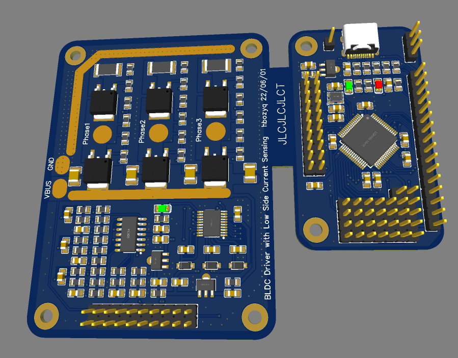
 motor EasyDIY ESC.png")