new eZip motor

Status
Not open for further replies.
Yea. Thanks.

That will put me on the right track.

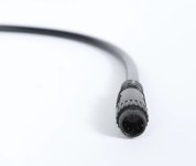
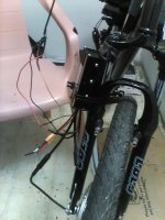
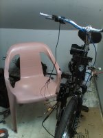
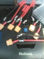
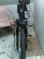
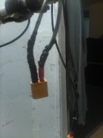
The 9 pin cable coming from the motor and controller are both way too short. It is why I had to extend the controller down and now is in the way of the fork when turning right. I need about an inch more so am about to slide the rack back a little.

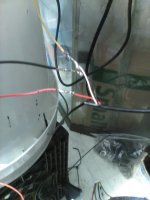
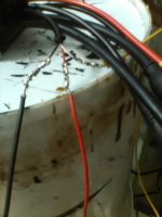
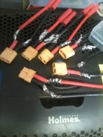
As far as the throttle It brings me back a few years when my friend Eric back in NY was stripping the gold pins from old computer parts for the gold plating. He was separating them according to the amount of gold. If I can find the correct size pins and then tape the female connecters together it would work.

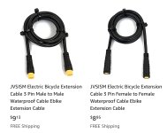
I am ordering the 9 pin extensions on Amazon for 12 bucks I can mount the controller where I originally wanted to about 6 inches higher, It will give me extra length for the throttle.

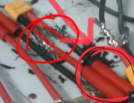
I just hope to find the pins. small solid copper wire is what I am searching for now. Some very thick 8 gauge cable sometimes has that and it is brittle and easy to break off.

frock it !!!!

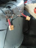
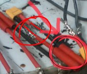
Sick and tired of setbacks on this build. I have been as patient as possible for me and now it will either work or it wont. No instructions came with the controller and no on and off switch so am wondering if it will even work if one of those other plugs is required to turn it off and on. :roll:

I might end up cutting more plugs off and splicing wires together before I am finished. does anyone have a clue. I went to e bikeling web site and did not find a wiring diagram or anything on the controller. I will try Bafang. Hopefully it is not all in Chinese. If it don't work today The motor , controller and throttle will find a new home in the garbage dumpster. :evil:

Thanks.

LC. out.
 

Attachments

  • IMG_0647.jpg
    IMG_0647.jpg
    263.2 KB · Views: 552
  • IMG_0648.jpg
    IMG_0648.jpg
    209.6 KB · Views: 552
Dont start jerry rigging shit together. Do it right the first time. Snip off that goofy f'ing connector and solder in some good connectors, XT90, XT60, 5.5mm bullets. Buy extra's!
I like the bigger bullet connectors because the solder bowls are easier. Others prefer the mechanical fastener route instead of solder, as its quick and easy but its more money for crimper tool but you seem full fledged into it as a hobby and still going at it hard. Maybe that lead solder smoke been tripping you up a bit. That gold pin, connector, 8awg talk is a bit trippy.
 
As the Hub Motor Turns and the LiPo Fire Burns. I confess for my sins of NOT listening to good advice and am changing some things.

Yea. It was about a month ago I think. I was in a big rush to go somewhere and was dark outside and could not see well but not an excuse and should have took the van and ended up that doing after.

Hooking the positive and negative together AGAIN !!!!! :oops: :oops: :oops: :oops:

Fortunately it was the OLD - 10P - 10S packs. I did it many times with the SONA packs but that time the 4P SONAs were in parallel with the 6P Samsung packs for 10P. I thought I taped the bullets together so it could not happen but must have forgot to do that when I paralleled the SONAs with the Samsung's.

The result was not catastrophic like the LG packs I built back in NY and lost 2 out of 4P with a small lithium fire and plenty of smoke. This time the bullets fused together and I cut my finger getting them apart on the sharp edge off the plastic that was broke separating the bullets.

I have in front of me xT60 male and female plugs.

IMG_0649.jpg

I ran the old 10P - 10S pack twice since and it seems that the short circuit protection in the Samsung packs did its job. I know the short circuit does work in the SONAs as I tested it several times with my stupidity. :oops: I still have a functional 10S - 10P pack but is less than 50% capacity and only good for about 5 miles round trip.

I will be soldering female XT60s to all positive and negative wires coming from my battery packs as well as fuses. Male XT60s will go to the wires coming from all my controllers. I already ordered two 40 amp and two 60 amp DC circuit breakers so I can finish these builds and have extra for any future upgrades and builds.

The 9 pin plug was just too short to mount the controller to the bike frame so had to mount it to the forks. The 9 pin connector kept coming unhooked when turning the wheel. I can live with it like that I guess. The only thing I can't live with is the handle bars. Basically if I can't fit the bike in the van I will never or hardly ever ride it. I will continue to ride the 20" bikes as refuse to haul heavy 26" motorized bikes up those stairs. It is just not going to happen.

Unfortunately I doubt I will be riding the 26" dual suspension unless I take the motor off the front. It is mounted to the handle bars and way too high to fit in the van. I am not sure but am thinking about taking the front motor off. That sucks but I am in no hurry to move when I only pay 375 bucks with all utilities included.

I ran out of solder. I guess I have to make a Wall-Mart trip. :roll:

thanks.

LC. out.
 

Attachments

  • IMG_0650.jpg
    IMG_0650.jpg
    246.3 KB · Views: 544
  • IMG_0651.jpg
    IMG_0651.jpg
    207.3 KB · Views: 544
  • IMG_0652.jpg
    IMG_0652.jpg
    229.7 KB · Views: 538
Thats apart of the problem when you have to start connecting and disconnecting a part of the battery to charge, then to connect and disconnect to use, and then disconnect and connect................over and over and over again.

Thats the same problem lipo has.

:kff:
No, thats not a middle finger, its Kentucky Fried Fingers, its what happens when you are careless, sloppy, tired, dim lighting, dont have glasses to see properly, in a rush. The stories are plentiful and common. But hey, KFF is not only related to flesh burns.... to one finger as the emoji lies to you, reality hurts more, burn covers more area, what tangent..... same goes for electrical components when its wired in/plugged in wrong, burnt arc welded wire and popping smoky batteries, crispy controller innards (if your lucky if not, hidden defect, can never be repaired..maybe). What you drank a case of beer, blurry vision, no no you got 4 more connects and disconnects and connects to go on cheap, janky, generic connectors to save a buck.

Hey its all good latecurtis, as long as you did not get KFF'd :kff:
Live & Learn


By the way, nice wire wraps for solder job, but can never forget to slide on the heat shrink BEFORE you solder.
I hate when I mess that up :lol:
 
IMG_0654.jpg

Well I have about 5 or 6 e bikes and several extra controllers all of which have male bullets for negative and female for positive coming from the controllers and two 10S - battery packs with male bullets for positive and female for negative already wired up.

Instead of cutting all those bullet plugs off and replacing with XT60 connectors it will be easier to just solder bullets to my XT60 plugs. The power wires from the batteries will go from bullet to female XT60s and the bullets from the controllers will go from bullets to male XT60s.

Then I just plug them into each and secure with a lot of electric tape so they do not come unplugged and should never have any more issues.

The problem is I guess I will be riding the 20" bikes until summer as the rate I am going it will take that long to finish these builds. As far as any 12S or 13S packs with 18650 cells , Maybe by next year this time I will have one built. :roll:

Thanks.

LC. out
 
ebikeling controller pinout:

ebikeling.JPG

Don't forget, you need the control panel! LED or LCD control module.
 
Sometimes we’re our own best enemy...
 

Attachments

  • 0D9C78E3-5285-468C-BA8E-A00E4893DEA9.jpeg
    0D9C78E3-5285-468C-BA8E-A00E4893DEA9.jpeg
    102.9 KB · Views: 509
ebikeling controller pinout:

This is a E bikeling moto controller and has the 9 pin plug for Bafang motors.

IMG_0658.jpgIMG_0657.jpg

Sometimes we’re our own best enemy...


I said in my last post I have about 8 or 10 or more controllers already wired up with bullets with a female bullet positive and male negative.

My battery packs are all many packs with bullets and custom parallel cablels I built to combine 3 packs to one and 5 packs to one positive male and negative female 4 mm bullet.. I would need about 30 XT60 plugs at least if I were to completely get rid of bullets which is ridiculous. I would not accomplish that in this lifetime. :lol:

So What I am doing is the next best thing. The bullets coming from each battery pack will plug into the bullets you circled in the picture with XT60 plugs on the other end and the bullets will be securely taped together. So when I am finished both battery packs The old 10S 10P and the new 10S 8P will have FEMALE XT60s and all my controllers will have MALE XT60S so no bullets will be in the equation when running and charging.

I just put 100 on my card and am ordering more XT 60 male and female plugs. The new solder iron is working great but should order the same iron with the extra tips as I have over 100 18650 cells to solder wires to and will probably be ordering a few hundred more.

Thanks.

LC. out.
 

Attachments

  • IMG_0655.jpg
    IMG_0655.jpg
    257.5 KB · Views: 504
  • IMG_0656.jpg
    IMG_0656.jpg
    260.8 KB · Views: 504
the Higo.
 

Attachments

  • 030F5D4F-214D-47AD-B735-8E07AF458042.jpeg
    030F5D4F-214D-47AD-B735-8E07AF458042.jpeg
    118.1 KB · Views: 508
DrkAngel said:
ebikeling controller pinout:


Don't forget, you need the control panel!
Don't forget, you need the control panel! LED or LCD control module. > "Display"

61kmdStN8TL._SS1000_.jpg
 
download (1).png

That is what my controller looks like and found a better spot to mount it. Too late on the throttle wire extensions. I already cut the plugs and soldered wires. It just got late and got a phone call that lasted about 2 hours and not feeling like working on it any more tonight. I still have not tested the Bafang motor and have another at the bike shop and still have to test that.


That was wrong (bottom pic) as there should be a male plug there and the bullets plug in to controller but could just as easily cut the bullets off each controller and put a male XT60. The female XT60 from the battery packs need to plug into the male XT60s from the controllers as well as the chargers.

I have a lot of controllers and four males so can do the bikes in the van as they each have 1 controller but the three dual motor bikes up here I am working on will need 6 male XT60s as each bike has two motors and controllers.

1. Giant Roam. - 2 - e bikeling motors.

2. 26" dual suspension. - 1,000W hub rear. 1,000W chain front.

2. Currie eZip Trailz. 36V 750W chain rear. - Bafang front,

Yea.

Still have not test drove the Giant Roam. All it needs is the rear brake hooked up.

One thing that I really like is evolving. I started building e bikes with one motor and brake. Now I build two motors and get two brakes hooked up. Usually. :lol:

20" bikes are just different because if you wear boots you got two brakes even if the bike don't have any. :lol:

I still will never sell my 700c bikes with perfect pedal gears. 2013 Giant Cypress Hybrid and 2016 Giant Roam.

Not sure what standards are required for 40+ mph but the Cypress (Easy Street needs a motor) That is my next build.

Like a MAC or BMC maybe. Hard to find though. Easy to get 3 Kilowatt chain drive. I am sick of installing chain drive motors.

I just uninstalled and re installed the 750W gear reduction motor on the Currie to get a rear brake. Could not have one before.

I succeeded but not without much trouble and still need to test everything. I did in fact tell all of you many times years ago that when anybody asks me about e bikes my advice always is that a hub motor is the best. UNLESS. You are good at go carts. Familiar with motor and wheel sprockets and have tools WITH mechanical skills. :lol: :lol:

I still will keep doing them anyway though I think. I am still dreaming about the 3 Kilowatt brushless motor. I still have the 1,800W brushless motor on the 20" bike in the van. 66V could maybe get me 40 mph with a better controller. :twisted:


Thanks.

LC. out.
 

Attachments

  • IMG_0659.jpg
    IMG_0659.jpg
    254.3 KB · Views: 484
  • download (3).png
    download (3).png
    153.4 KB · Views: 482
No heat shrink on the bike pic with the XT60 to the right. You have a ton of room to slide on the heat shrink upwards, solder, slip heat shrink down over joint and shrink the heat shrink. Hmmmm my guess is that XT side is 10awg, black wires 12.
 
You need to learn how to do a linesman's splice to join two wires together. Even though your wire wrap is neat, once soldered, all the force if you pull on rhe wire is then on the solder and eventually you can get a bad join.

A linesman's splice puts the stress on the wire itself, and it has been proven even without solder, the join is stronger than the wire itself.

Unfortunately for you with such a difference in gauge, a linesman's splice will be hard to do, and you may need more length of wire.

images
 
No heat shrink on the bike pic with the XT60 to the right. You have a ton of room to slide on the heat shrink upwards, solder, slip heat shrink down over joint and shrink the heat shrink. Hmmmm my guess is that XT side is 10awg, black wires 12.

IMG_0660.jpgIMG_0661.jpgdownload (1).png

I tried the linemans splice but these XT60 plugs are way too short. I did a lot of linemans splice with no solder on a lot of the motor wires. The trick is to cut long 10" strips of electrical tape and then hang each from the handle bars and then cut the strips in half so they are thinner then wrap that tape around the linemans splice about an inch and a half before the start and the end of the splice.

I soldered both sides for extra strength. I used a lot of solder. That black stuff is the liquid electrical tape. Tomorrow when it is totally dry I will wrap thin strips of regular electrical tape.

I ordered another 5 pack of male and female XT60s. I have 3 dual motor bikes so had to order that Y connecter. The wires on the handle bars are female to male extensions The female plugs into the male from the controller and the male into the Y connecter. On the bucket is the bullets to XT60 female which will plug into the battery packs and the bullets will get taped off and no longer used. There are two. One for each pack. The third will hook up to the brush controller which has bullets, Those bullets will also get taped off and the male XT60 plug will plug into the other extension cable.

Basically the Y - XT60 connecter can plug into the two extension cables and get taped together. That way I can use that for any of my three dual motor builds. I am far from being done however as I got circuit breakers also for each controller all of which will need XT60s. Also am considering a power meter which will need to hook to the battery packs before the dual motor Y plug so the female plug coming from the packs will plug into a male going to the power meter and a female coming out of the power meter to the male Y plug which has two female plugs for the extensions going to both controllers.

I really can not simplify things any more than that because I have two bikes in the van I am also converting to XT60 plugs. The only thing I could do is use the same power meter for all bikes and the single motor and controller bikes in the van will not need the Y XT60 adapter but can still plug into the power meter. All I will have to do is cut two zip ties every time I move the power meter from one bike to the next unless I can use some Velcro strap.

When I am finished I will have five functional e bikes. Three dual motor and two single motor and can use the power meter with all five e bikes. Since the bikes are all of different power levels I will have a DC circuit breaker for each one so cant even count how many XT60s I will need. I will have to do 1 or two bikes at a time. I got a head ache figuring that all out. It is one of the reasons I did not work on the bike until a couple hours ago.

I said I was doing a lot of upgrades on these e bikes this winter. I was not lying. Is there a speedometer that is wireless I could also move from one e bike to another. It would be great NOT to have to buy a separate speedo. for each bike. Please let me know. I will look online too. I see wireless speedos but still requires a magnet. How about an android app. for my phone for GPS in google maps. A speedo. app. would need to be clear and bright for videos. I have a mount for the handle bars for my phone. Please let me know.

I am looking at a camera that can strap to my forehead. The cheap Wall-Mart one had that option but I could not figure it out and smashed it as It failed 3 times to transfer video to my computer.

Thanks.

LC. out.
 
Liquid Electrical Tape is not the stuff to be using on that. Its really not that great a product. You'd be better off using Epoxy.
I'd wrap your liquid electrical tape in normal electrical tape plenty of times.
Just do it right the first time, I see on the one pic you got plenty of wire to use heat shrink on without the heat of the iron soldering the wires together shrinking the heat shrink. The other pic you dont have much room at all, with the 4mm bullet housing and XT60. But yeah you better do more then just electrical liquid tape. I have used 2 cans of that stuff, and over time it comes off, plus the added heating and cooling due to electric current. Then the freezing if its winter time, just peels off over time.
 
Liquid Electrical Tape is not the stuff to be using on that. Its really not that great a product. You'd be better off using Epoxy.
I'd wrap your liquid electrical tape in normal electrical tape plenty of times.

Yea. Auto zone only has packs of shrink tubes with all different size. I would need to buy at least a half a dozen to get enough of the right sizes. I should have ordered online but will be wrapping a lot of thin strips of electric tape to do the job.

750 + 350 = 1,100 W for total motor output both motors. It will run fine off one of my 10S packs. The new packs are about 8P I think and it will work.

The Giant Roam is two 500W e bikeling motors which will also work with just the new pack and the Y - XT60 connecter. The 26" dual suspension will require me to run both the 10S - 10P packs for one motor and the new 10S - 8P packs for the other motor. The #25 chain to hook the front motor up is here for me to pick up. I have a 60 amp DC breaker for the 1,000W hub motor and ordered two more 60 amp breakers. One for the front 1,000W chain drive on the dual suspension and another for the 750W gear reduction motor on the back of the Currie. A 40 amp will be used for the Bafang motors. I ordered two of those also.

I am hoping to get these two dual motor e bikes finished soon. By the looks of the weather I won't be testing them out any time soon. It is snowing out. Not sure how much we are getting. I do know however both dual motor bikes will have XT60s for run and charge. Both will also have both brakes front and rear and both will have perfect gearing as they are both dual motor e bikes which could run on a single motor if one motor were to go down. I just might have to walk up a steep hill with the currie if only running the front Bafang motor.

Thanks.

LC. out.
 
latecurtis said:
750 + 350 = 1,100 W for total motor output both motors. It will run fine off one of my 10S packs. The new packs are about 8P I think and it will work.

Your motors' wattage ratings don't matter so much. It's about how many amps your controllers will draw, combined. Do you know what that number is?
 
our motors' wattage ratings don't matter so much. It's about how many amps your controllers will draw, combined. Do you know what that number is?


No but think the power meter I have will show it. It is why I want to hook up XT60 plugs so I can easily move it from one e bike to the next.

I guess it would be possible to hook the old 10S - 10P packs in parallel with the new 10S - 8P packs for one large pack but the 10P packs are defiantly < 50% capacity as when they were new. How would that work out ?????


I cut one 8 or 9" strip of electrical tape into 3 thin strips and that is what it looks like compared to the other side I still have to do.

I will leave a little red insulation showing on the positive side but the rest will look like the negative side.

Thanks.

LC. out.
 

Attachments

  • IMG_0662.jpg
    IMG_0662.jpg
    143 KB · Views: 397
I guess it would be possible to hook the old 10S - 10P packs in parallel with the new 8S - 8P packs for one large pack but the 10P packs are defiantly < 50% capacity as when they were new. How would that work out ?????

Not well. A 36V battery charged to 42V in parallel with a 28.8V charged to 33.6V. I mean there is a way to do it but its not a good way of doing it, but how much capacity would you have, even if you just wanted to use it for a tiny bit without draining bigger battery to much. If your batteries have a bms for lvc I guess it wouldnt matter, if you plug them in parallel at the correct voltages. Just dont count on your controller lvc to save a battery for mix & match day. Connecting a battery in parallel is the exact same thing as connecting your 18650's in parallel, they have to have the same voltages otherwise there is a major surge from one battery to the other battery to equalize both sides. Thats what paralleling is. 0.01V is a good difference, 0.05 is fine to. About the max is 0.1V.
 
No. it was a misprint.

The old and the new packs are both 36V empty and 42V full charge.

They ate both 10S packs.

The old packs were 4P SONA packs. two 4,4 AH - 2P packs.

I bought 3 - genuine Samsung 4.4 AH packs so three 2P Samsung and two 2p SONA so 10P total but well over 100 charge cycles.

The new packs are 8P I think. two 4 AH - 20 cell packs in parallel with a 4P pack so 8P - 10S.

https://www.youtube.com/watch?v=5CI3K1Wd21o

all three strips are used. I start with the first starting at the plug and stop about an inch after the solder joint. The second I start after the solder joint and wrap towards the plug and then the last is at the plug to an inch and 1/4 after the solder joint.

It is a little tedious but I know they will never short out and will be better than shrink wrap by itself.

Thanks.

LC. out.
 
Video - There is no real need to slice the electrical tape into thirds lengthwise, your just making it harder for yourself, making more work, you must be in the union of tape cutters. Yes its true you'd have to cut the tape in order to wrap it around but you can use full width electrical tape. Its better to use full width, because theres more overlap, means more layers. Well heat shrink is more desired and you can double and tripe layer the cheap thin walled heat shrink, or spring for the thicker walled heat shrink which costs more. Electrical tape is temporary for something like that. Lets just hope your solder joints dont have any peaks of solder that will break through tape. Like when you raise the soldering iron off the joint, sometimes if your not careful peaks can arise, like a pin or a nail sticking out. Fun times.
 
That is the least of my worries.

The motor or the controller does not work. I tested the plug going to the controller so is not the switch or the fuse.

download (3).png

download (2).png

IMG_0664.jpg


That is what is missing but do not understand why the plug is that teal color and not red.

The plug on the controller is red.

I have no idea what that big plug is for ?

This really sucks. I will have to go pick up the motor at the bike shop then before they start charging me storage or something. It looks like a lost cause. These motors will sit in a corner forever collecting dust I guess.

A lot of work for nothing. :cry: :cry: :cry: :cry:

Thanks.

LC. out.
 
Not really sure what the deal is, so your connectors do not plug in to each other, mis matching connectors will do that. I like to buy my connectors in pairs. On hobbyking you can buy male or female xt's or pairs. Thats the problem with buying from different places. Thats like buying XT60 male from Hobbyking and XT60 female off Amazon and hoping they fit, knowing full well each one is counterfeit, probably made off a 3d printer in some basement somewhere with an Amazon account. The good news for you is Grintech sells pairs of genuine XT60's, along with some other types of connectors, probably be a cool week before it arrives.

I've plenty of times hard wired (soldered) phase wires together without any connectors, hard wired throttle wires together to. Once out riding I had a solder joint break on me in the parallel/series harness and had to use electrical tape alone on it to get me home more then once. Spent the $5 for a few feet of electrical tape from gas station. Talk about babying the throttle so no current spike through joint, fun times huh. You dont always get lucky and have enough wire to twist, sometimes you just gotta lather on the electrical tape and hope it stays. You know the slogan, the more the merrier.

Time to get the wire cutters out, and plug in your ole soldering iron.
 
As labeled in the controller I pictured, the red 2 pin connectors are for the brake disconnect! LED MODULE "Display" SHOULD HAVE 5 PINS!
 
Look like the connector you need?


Attachments

  • ebikling cable.jpg
    ebikling cable.jpg
    10.5 KB · Views: 328
Status
Not open for further replies.
Back
Top