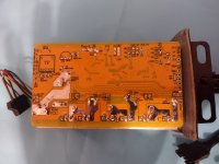
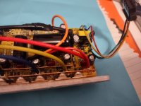
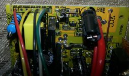
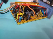
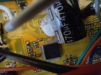
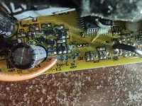
R12 mod for high voltage regen

Hugues said:
my board is different, if i ground the BK pad, throttle is deactivated and regen activated.

Probably i'm going to say something stupid here, but how about this method to play with the level of regen:
- if i press my brake lever, regen is activated, if i release, regen stops
- so in theory i can press and release fast enough to play with the level of regen
- but that's not very efficient
- how about we build a simple circuit doing just that, it flips the BK pad on and off, at the right frequency and you could adjust the UP time.

Would this make the regen level changes ? or just blow up a hole in my underpants due to sudden LiPo explosion ?
PWM on top of PWM :wink:
Leverage a HE sensor to vary the width between pulses :)

Neat idea, KF
 
Somewhere around here there's a thread where I proposed doing that, replacing the switching hall sensor in a brake lever with an analog one out of a hall throttle, using that to control a small PWM circuit that would then toggle the ebrake line.

I havent' pursued it yet mostly due to time, but also because the controller would have to be modified inside, if it is even possible: All of the cotnrollers I have used so far take significant time (up to a whole second!) to respond to the ebrake input, so any PWM would have to be a minimum of pulse length to match the response time of the controller. Any shorter pulse isn't responded to.

So it would only do any good on very long braking stretches, like a long downhill run, and does not have time to do anything at all on short braking for typical stops or traffic slowdowns and the like.

The other issue is that even on the long downhill runs, you will basically get full-strength braking pulses, spaced apart by however long it takes your controller to respond to an input. Each pulse would be as long as the PWM input told it to be, plus whatever the ebrake's response time is (because at least some controllers *also* take time to *release* the brake, as well as to engage it).


So except for some of the controllers being designed around here that may have this type of thing built in by popular demand (like RickyNZ's) or that might have it added easily (Jeremy Harris'), it would not practically work on most of the typical ebike controllers out there, for most of the situations in which it would be desirable (for me, at least). :(
 
Kingfish said:
I am curious to know if there anyone else running slip-mode, and if they can confirm or share the behavior. :)
It depends on the controller, too. I have a 36V Ecrazyman type generic 12FET (not sure if it is programmable) that by default uses this method, whcih is also called Demand-Speed Control, which under no-load conditions appears to engage braking proportional to the throttle position, but under load (ride) conditions doesnt' appear to do anything other than act like a normal throttle. :?

Some controllers in this mode will actively brake full-on when throttle is moved below the speed previously demanded, for any throttle position.

Some controllers in this mode will do the above, but if throttle is just snaped all the way off quickly, it does freewheel, unless ebrake levers are engaged, at which point it brakes full-on.

Some controllers in this mode respond normally to throttle in all throttle positions except when ebrake levers are engaged, at which point the throttle becomes a braking modulation control, instead of a throttle.

None of them so far as I know do it the way I want it to do, which is to let an ebrake analog-voltage input control the braking modulation. :(
 
Hugues, you say you have a different board, but did not say what yours is...do you have a model number on it?
 
NeilP said:
Hugues, you say you have a different board, but did not say what yours is...do you have a model number on it?
EB712XC

For me the dream throttle would be:
- twist counter clockwise: bike speed is increased
- bring it back to zero point: motor is disengaged completely
- twist clockwise: regen braking engages, the more you twist, the more it brakes

Until my dream is realized, I could well do with:
- left brake lever engages regen braking and twisting the throttle varies its power
I say left brake because I feel it quite tricky to brake on right at the same time as operating the throttle.
 
Ok, so someone might recognise those serial numbers..lets hope.

But I gad alway s read that you must have BK connected to allow breaking to work... and then you brake using the EBS- pad...but looking at my Crystylate board...it does have e-braking connected toht eh EBS- pad..but there is no wire at the BK pad at all...the hole is empty.


So can't really help any more, sorry
 
Very old thread but I'm trying to find out how to increase the maximum regen on an Infineon 4 style KH6 programmable controller. The maximum value I can set in the software is 77.6V and it sounds like the "R12" mod may be what I need to go beyond that limit however I don't even know if the Xie Chang Infineon 4 style KH6 controllers have an "R12" resistor to change. :?:
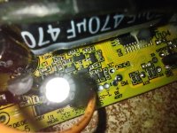
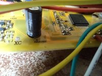
IMG_20220308_204652408.jpg
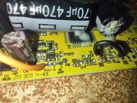
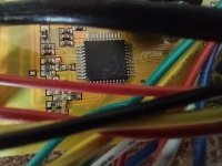
IMG_20220308_204630978.jpg
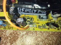
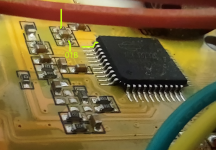
IMG_20200901_141000 (1).jpg
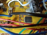
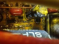
IMG_20220308_095929777.jpg
 
All controllers have something like the "R12", in that they all have a voltage divider somewhere for the MCU to know what battery voltage is, so they can monitor for LVC and HVC, at minimum (and some monitor voltage to put on a display readout or for other purposes, too).

If you look at the pins from the MCU, you'll find one that leads to a volage divider, which will generally be a pair of resistors in series from battery positive to ground (the connection between the two resistors will be what the MCU pin connects to). There may be other electronics (op-amp, etc) between the divider and the MCU, but since those add cost it's more likely to be a direct connection, with at most a single extra resistor between the MCU and the series tie-point).

The actual parts are probably right next to the MCU itself.


Changing either resistor in the series connection changes the voltage that results at the MCU pin; it's basically just reducing the battery voltage by a ratio sufficient to keep the MCU pin safe (probably under 3.3v, sometimes under 5v). So whatever change you make needs to still keep that voltage below the limit of the MCU pin, whatever that is for that specific MCU.
 
Thanks for your reply amberwolf,

I'm struggling to understand and locate these resistors for a voltage divider you mention that will likely be near the MCU. Here is a better shot near the MCU; any ideas?

IMG_20220418_154121183.jpg
IMG_20220418_154052413.jpg
IMG_20220418_154037128.jpg
 
For comparison sake: here is my larger controller (also an Infineon 4 / Xie chang/ KH6xx) where regen does work above the 77.6V limit:

IMG_20220418_144720115_HDR.jpg
IMG_20220418_144800470.jpg
IMG_20220418_144836805_HDR.jpg
 
Any paired set of resistors could be the divider in question.

One end of the pair will connect to battery positive (probably at the "keyswitch ignition" side, rather than the main battery positive input), and the other end of hte pair will connect to ground (battery negative). The center of the pair will connect to the MCU, either directly to a pin, or via another resistor (or some active components like an op-amp).
 
amberwolf said:
Any paired set of resistors could be the divider in question.

One end of the pair will connect to battery positive (probably at the "keyswitch ignition" side, rather than the main battery positive input), and the other end of hte pair will connect to ground (battery negative). The center of the pair will connect to the MCU, either directly to a pin, or via another resistor (or some active components like an op-amp).

I've done some more poking around on the larger controller because the smaller one I'm trying to modify has a capacitor obstructing the MCU pins. I've found that this pin (highlighted in green) from the MCU is the only one with continuity to ground (battery negative). No other pins seem to have continuity to battery negative or battery positive. The two tiny resistors read "01B" which I've found means 1kohms. Could I be getting close?

KH618-MCU.png
 
It's possible that the divider is somewhere else on the board, rather than near the MCU.

Also note that the board that doesn't have the limit might not have *any* limit because it might be wired with a static voltage at the battery-monitoring input, so there wouldn't be a battery-voltage-level anywhere on the divider, in that case. If so, you would only be able to find the right resistors on the board that does have the limit.

I tried to find info on the XCK J3232C MCU that is in the picture of one of your controllers, but according to Infineon / XieChang it doesn't exist. :(

Here's an appnote for one of the XC chip dev boards for XC836M :
https://www.google.com/url?sa=i&url=https%3A%2F%2Fwww.infineon.com%2Fdgdl%2FInfineon-Evaluation_board_300W_motor_control_application_kit-AN-v01_00-EN.pdf
(also attached)
that says pin 1 (U1-1) is the Vref 0v-5v range input that is used to monitor battery current. Maybe they're usign the same pin on the chip you have there, if you're lucky.

Some other similar results that may have schematics and appnotes that could help
https://www.google.com/search?q=knuckles+infineon+bldc+r12+schematic&tbm=isch&ved=2ahUKEwiL6NbdtqD3AhWQGDQIHbIqB4AQ2-cCegQIABAA&oq=knuckles+infineon+bldc+r12+schematic&gs_lcp=CgNpbWcQA1DtCVidHGDhHmgAcAB4AIABZ4gBrgSSAQM0LjKYAQCgAQGqAQtnd3Mtd2l6LWltZ8ABAQ&sclient=img&ei=TdNeYsuNEJCx0PEPstWcgAg&bih=848&biw=1537
 

Attachments

  • Infineon-Evaluation_board_300W_motor_control_application_kit-AN-v01_00-EN.pdf
    1.5 MB · Views: 17
I've been spending time looking at both controller for any clues on what resistor to change and most of the resistors appear to be the same values on the limited vs non limited controller. Also, I've confirmed they are both using an XCK J3232C chip.

I've contacted Grin as they said they used the same chip in their Grinfineon controllers (different firmware) but I haven't heard back. Surely there must be some who has played with this chip / controller?
 
I've spotted a difference on the two boards:

**interesting pin highlighted in green

on the limited controller this mcu pin goes to a resistor (10k ohms) which goes to???
IMG_20220422_143618458_HDR.jpg
Note to self: 4th from top on left side of mcu seems to fluctuate with battery voltage 2.8 -3.8V

on the unlimted board, there is no apparent connection to that same mcu pin
IMG_20220422_142821711_HDR.jpg

Could that be it?
 
Measure the voltage at the pin. If it doesn't change with battery voltage, it isn't the pin monitoring it.

(whenever reverse-engineering something, or troubleshooting, think about the function you're working on/with, and what you would expect to find at each point, or at least at the start of the circuit and the end of the circuit; what is it supposed to do, and that lets you figure out a measurement you can use to determine whether you foudn the right point or not. ;) )
 
Thanks again for your reply amberwolf. I've found some promising clues on the limited board. I've also found that multimeters only beep on continuity mode if the resistance is under a certain value (I've only had this tool for nearly 15 years haha).

The forth pin from the top on the left side of the MCU. This pin on the MCU seems to move with the battery voltage when probed at the ground + that MCU pin. The voltage reading I was getting was ~2.8V @ 50V battery and ~3.8V at 58V battery.

That MCU pin goes to a 122 resistor. That resistor then connects to a tiny brown square capacitor (I think) and then to an 85B (7.5k ohms) resistor. I checked on the "unlimited" controller and the resistor is a 1692 (16.9k ohms) - hopefully that is it! It goes to one more resistor and then VCC or battery voltage.

Off to do some more testing
 
It works! Here is the 7.5 k ohm resistor that I changed to a trim pot/variable resistor:
IMG_20220423_082217564_HDR.jpg
It remove that first capacitor so I had room to use my soldering iron

I had to adjust the LVC on the controller after this modification

Thanks amberwolf
 
I have a question about a decent quality 18fet infinion kh6 clone i brought used i was expecting to have to do the r12 mod to allow regen at 92v but to my surprise it just works should i be worried? i was expecting a 77v limit as that was the highest i could turn it up to with xpd but it regens fine feels perfect
 
If the FETs and capacitors, etc., are rated at a high enough voltage above the max battery voltage (say 20-50% higher, at least), and the system works normally, there shouldn't be much to worry about.

The problems with (higher voltage) regen come from:

--BMS shutting off due to HVC when regenning into a full or nearly-full battery; when this happens the load disappears and the voltage on the controller FETs can suddenly be left at much higher voltage than they were, higher than they can handle, and the FETs can blow.

--elecrical noise spikes during normal operation can be high enough to exceed the margin between nominal battery voltage and the max FET voltage limit...and that can blow the FETs too.

FETs usualy fail shorted, which then locks up the wheel (or puts a lot of resistance on it; significantly higher than that caused by regen; depends on how many phases blow this way).
 
Back
Top