
You are using an out of date browser. It may not display this or other websites correctly.
You should upgrade or use an alternative browser.
You should upgrade or use an alternative browser.
Smart EBike: Dashboard + Motor controller + Battery BMS
- Thread starter casainho
- Start date
grindz145
1 MW
Sweet little dev board is that LPC2103 processor an ARM9?
Edit oops I was 3 pages behind...
The board is looking really good!
Edit oops
The board is looking really good!
casainho
10 GW
- Joined
- Feb 14, 2011
- Messages
- 6,047
No, it is "old" ARM7, but really cheap. Should be more than enough to the task and I can change at any time if needed.grindz145 said:Sweet little dev board is that LPC2103 processor an ARM9?
casainho
10 GW
- Joined
- Feb 14, 2011
- Messages
- 6,047
I think we need OpenSource controller AND with commercial/professional support.Arlo1 said:Just found this thread. Very cool we need more diy controllers!!")
casainho
10 GW
- Joined
- Feb 14, 2011
- Messages
- 6,047
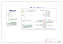
I am finding difficult to understand BEMF circuit and needed firmware and so I decided I will build a working prof of concept controller using hall sensors. I will use KU63 plus ACS756SCA-100B (current sensor) and the Bluetooth UART module.
I started to draw some schematics and put them on github:
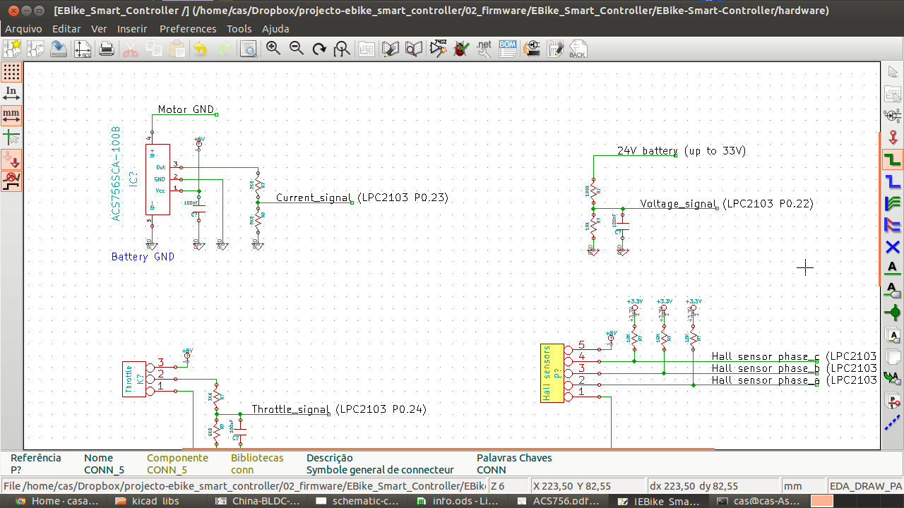
I started to draw some schematics and put them on github:
Attachments
casainho
10 GW
- Joined
- Feb 14, 2011
- Messages
- 6,047
I bought and received the current sensor ACS756SCA-050B. It is expensive, it costed to me about 10€.
I will exchange the shunt resistor used on KU63 for measure the current with the ACS756SCA-050B. This way I will be able to measure the current on the controller and calculate the power used by the motor and the ratio of Power VS Speed.
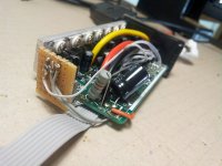
Here a picture showing the will be simple and quick to place the current sensor ACS756SCA-050B on KU63:
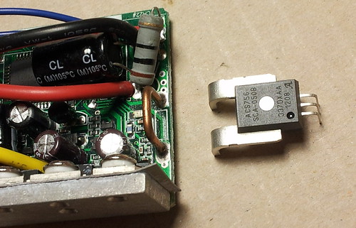
I will exchange the shunt resistor used on KU63 for measure the current with the ACS756SCA-050B. This way I will be able to measure the current on the controller and calculate the power used by the motor and the ratio of Power VS Speed.
Here a picture showing the will be simple and quick to place the current sensor ACS756SCA-050B on KU63:
casainho
10 GW
- Joined
- Feb 14, 2011
- Messages
- 6,047
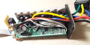
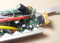
Finally I added the current sensor to KU63 and changed the resistor for voltage measure. I also removed all the wires used by KU63 for hall sensors, brake, throttle, etc, as they aren't needed anymore, since this will be on main board - now KU63 board is more clean.
There are 10 wires leaving KU63 board that will connect to Ebike Smart controller main board:

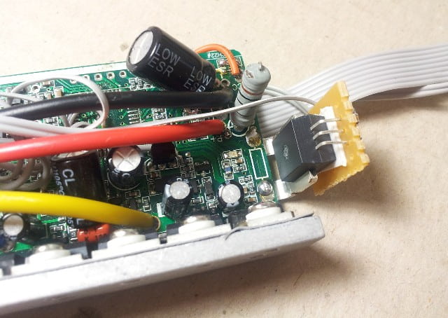

There are 10 wires leaving KU63 board that will connect to Ebike Smart controller main board:
Attachments

casainho
10 GW
- Joined
- Feb 14, 2011
- Messages
- 6,047
Last time I wanted to go with Hall sensors and avoid BEMF since it is difficult to start with. But quickly one Hall sensor of my motor stoped to work -- maybe I made some short circuit with it. I am now back to BEMF.
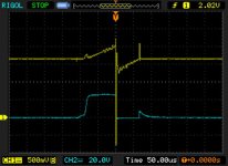
On my motor Cute 85, 24V, 250W, I can energize it by 100us and found the position of rotor/sector. Energizing 100us I only get current on 2 sectors (one getting more current than the other). Using like 500us I will get current in all sectors however the current on the 2 aligend/"strong" sectors will be to much high!
Here is a screenshot of my scope:
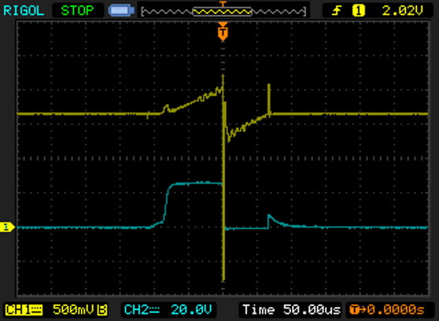
Yellow: current signal
Blue: mosfet gate voltage
The sector with the higher current is the one aligned and now the rotor position was found. Next I need to work on code to startup the motor, as explained on many application notes and also by walls99 on Open Sensorless BLDC controller.
On my motor Cute 85, 24V, 250W, I can energize it by 100us and found the position of rotor/sector. Energizing 100us I only get current on 2 sectors (one getting more current than the other). Using like 500us I will get current in all sectors however the current on the 2 aligend/"strong" sectors will be to much high!
Here is a screenshot of my scope:
Yellow: current signal
Blue: mosfet gate voltage
The sector with the higher current is the one aligned and now the rotor position was found. Next I need to work on code to startup the motor, as explained on many application notes and also by walls99 on Open Sensorless BLDC controller.
Attachments
Jeremy Harris
100 MW
casainho said:KUxxx controllers seems to be optimized for cost and are complex for me to understand, also they can't measure current only the maximum current -- I really want to measure current and voltage.
FWIW, the shunt is the current sensor on the KU series controllers, and drives two independent current sense circuits, so the controller does in fact sense voltage and current linearly (as do all the other ebike controllers I've seen). One of these current sense circuits is an A/D input on the µcontroller that does the normal linear current limiting function, so that there is a smooth reduction in PWM duty cycle as the battery current tries to increase above the set limit. The other is a fault detection over-current sense circuit, that uses an internal comparator in the µcontroller to shut it down, via an interrupt, if a fault condition is detected.
I agreey with njay, the FET gate drive voltages need to be kept down well below 20V. 12 to 15V is fine for gate drive.
casainho
10 GW
- Joined
- Feb 14, 2011
- Messages
- 6,047
Njay, I am using the KU63 circuit and giving it the control signals, please find here the PDF schematic of KU63: http://www.avdweb.nl/solar-bike/electronics/ku63-motor-controller.htmlNjay said:Not directly related to your comment but, most MOSFETs have an absolute maximum of +/-20V between gate and source and you have "gate signals" of some 24V; what and how are you exactly measuring on the yellow line?
The yellow line is the voltage output of the current sensor, after a voltage divider (since my controller uses 3.3V and not 5V on ADC Vref). Here is the schematic I am using the the current sensor:
Attachments
casainho
10 GW
- Joined
- Feb 14, 2011
- Messages
- 6,047
Yes, you are correct. I am now using ACS756 sensor, is expensive but I may be able to measure current in steps of 500mA (or less) and I need it because I want to calc the power usage by the motor and show it to user. This expensive sensor is good for DIY circuit prototype/development.Jeremy Harris said:casainho said:KUxxx controllers seems to be optimized for cost and are complex for me to understand, also they can't measure current only the maximum current -- I really want to measure current and voltage.
FWIW, the shunt is the current sensor on the KU series controllers, and drives two independent current sense circuits, so the controller does in fact sense voltage and current linearly (as do all the other ebike controllers I've seen). One of these current sense circuits is an A/D input on the µcontroller that does the normal linear current limiting function, so that there is a smooth reduction in PWM duty cycle as the battery current tries to increase above the set limit. The other is a fault detection over-current sense circuit, that uses an internal comparator in the µcontroller to shut it down, via an interrupt, if a fault condition is detected.
Hmmm, I need to see if there is some problem with KU63 controller... here is the PDF schematic of KU63: http://www.avdweb.nl/Article_files/Solarbike/Motor-controller/China-BLDC-motor-controller-36V-250W.pdfJeremy Harris said:I agreey with njay, the FET gate drive voltages need to be kept down well below 20V. 12 to 15V is fine for gate drive.
Jeremy Harris
100 MW
The standard KU series controllers use a 10 bit A/D and can measure current down to under 500mA. They are resolution limited by the A/D max range and the inevitable noise on the supply line, but I believe they use the internal 1.24V reference in the µcontroller to set the A/D range, so 1 bit is around 1.2mV. This gives a current resolution of around 0.3A for a 4 mohm shunt. It's debatable if you need better than 1/2A resolution for limiting, anyway, IMHO.
I found that it was perfectly feasible to measure the voltage across a 4 mohm controller shunt and use it to provide a display of power that was accurate enough for most purposes. My original simple battery "fuel gauge" does this to calculate Ah used (there's a thread here somewhere describing it).
I found that it was perfectly feasible to measure the voltage across a 4 mohm controller shunt and use it to provide a display of power that was accurate enough for most purposes. My original simple battery "fuel gauge" does this to calculate Ah used (there's a thread here somewhere describing it).
casainho
10 GW
- Joined
- Feb 14, 2011
- Messages
- 6,047
I understand what you said. If someday I will design something commercial/cost optimized, I will use this info.Jeremy Harris said:The standard KU series controllers use a 10 bit A/D and can measure current down to under 500mA. They are resolution limited by the A/D max range and the inevitable noise on the supply line, but I believe they use the internal 1.24V reference in the µcontroller to set the A/D range, so 1 bit is around 1.2mV. This gives a current resolution of around 0.3A for a 4 mohm shunt. It's debatable if you need better than 1/2A resolution for limiting, anyway, IMHO.
I found that it was perfectly feasible to measure the voltage across a 4 mohm controller shunt and use it to provide a display of power that was accurate enough for most purposes. My original simple battery "fuel gauge" does this to calculate Ah used (there's a thread here somewhere describing it).
You know a lot about KU controllers!! I couldn't found any datasheet for the X8M06-C controller.
casainho
10 GW
- Joined
- Feb 14, 2011
- Messages
- 6,047
Finally I did the code that identifies the rotor position/sector. I tested it and seems to work well:
Code:
unsigned int rotor_find_position_sector (void)
{
  unsigned int sector_current[6];
  unsigned int max_current = 0;
  unsigned int max_current_sector = 0;
  unsigned int i;

  motor_set_duty_cycle (1000);
  for (i = 0; i < 6; i++)
  {
    commutation_sector (i + 1); // start energize the sector
    delay_us (50); // wait 50us

    // read the current, 4 samples and average/filter
    sector_current[i] = 0;
    sector_current[i] += (adc_read (CURRENT) / 4);
    sector_current[i] += (adc_read (CURRENT) / 4);
    sector_current[i] += (adc_read (CURRENT) / 4);
    sector_current[i] += (adc_read (CURRENT) / 4);

    commutation_disable ();
    delay_us (50); // wait 50us

    // verify and save the higher current sector
    if (sector_current[i] > max_current)
    {
      max_current = sector_current[i];
      max_current_sector = i + 1;
    }
  }
  commutation_disable ();

  return max_current_sector;
}May not be that important in this application but that's not a good average, you're loosing data. The integer binary divide always rounds down. So you should add all up and divide at the end - even better, round by adding half divisor prior to divide. Further it's less efficient, you're dividing 4 times instead of 1.
casainho
10 GW
- Joined
- Feb 14, 2011
- Messages
- 6,047
Thanks! I may update later this piece of code. For now, it is here: https://github.com/casainho/EBike-Smart-Controller/blob/master/firmware/bldc.cNjay said:May not be that important in this application but that's not a good average, you're loosing data. The integer binary divide always rounds down. So you should add all up and divide at the end - even better, round by adding half divisor prior to divide. Further it's less efficient, you're dividing 4 times instead of 1.
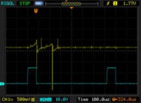
And the array sector_current[6] don't need to exist. Later the code can be optimized. For now I am not being able to start the motor :-(
Here is the current signal resulted from that code (sector 1 with higher current, aligned):
Attachments
casainho
10 GW
- Joined
- Feb 14, 2011
- Messages
- 6,047
I have luck to found a person that lives near me and have a lot of experience and tools for electric scooters. He have a big garage!!
This guy asked me advice for selecting hall sensors to a motor he is repairing - he already changes hall sensors in motors of scooters. He also built already battery packs for electric bicycles and scooters. He will help me repairing my motor by adding a new hall sensor and so I plan to go back to hall sensor code and avoid the BEMF that is complex.
Here some pictures from this guy garage/motor:
casainho
10 GW
- Joined
- Feb 14, 2011
- Messages
- 6,047
Eheh, yes, it is JorgeNjay said:Às tantas é o Jorge
Another guy from Portugal here, oh great!! I will contact you by PM.
casainho
10 GW
- Joined
- Feb 14, 2011
- Messages
- 6,047
I just disassembled my motor (Q85/Cute85) to try see if I can repair the faulty hall sensor. Seems it will be easy but I need to buy a compatible hall sensor(original hall sensor: AH61)! Here the picture of the inside motor:


I also have a "dead" 48V 15Ah battery and I am trying to fix it. It is very nice all this experiences because I am getting a better understand of all the system. It is very important for me to see the motor inside and try understand how to control it
I also have a "dead" 48V 15Ah battery and I am trying to fix it. It is very nice all this experiences because I am getting a better understand of all the system. It is very important for me to see the motor inside and try understand how to control it
casainho
10 GW
- Joined
- Feb 14, 2011
- Messages
- 6,047
I changed the dead AH61 hall sensor on the motor by on AH175-PL-A-B that I got on Farnell. It works perfectly. Also my friend Jorge used the same AH175-PL-A-B sensor on his electric scooter motor and it works.
With the latest firmware I got the motor working and reacting to changes on PWM as expected, that changes the velocity. The only problem is that motor runs in inverse direction... and I were not able to make it run on correct direction. Cute85/Q85 motor that I am using have a kind of freewheel on rotating on inverse direction it doesn't make torque, I can stop it by hand.
I hope to have the motor working soon! and then I will add the throttle and brakes functionality (should be easy and quick) and finally the Bluetooth communications with the Android
casainho
10 GW
- Joined
- Feb 14, 2011
- Messages
- 6,047
Help to start up the motor Cute85/Q85 using the Hall Sensors
I can't start up the motor using the Hall Sensors! I have current sensing control working and I setup it to be 8 amps (I am verifying that with the oscilloscope).
I decided to understand why it doesn't start. I am energizing phase A with + and phase B and C with - during 100ms, with 8 amps (not using any hall sensor signals). After 1 second I exchange to others phases, like "rotating". The motor gives a "kick" at each second sometimes and others don't - I verify the current with the oscilloscope to control and see that electrically it works as expected.
When it gives a kick it rotates but when it goes to some position where it doesn't give a kick/moves, it stops there forever (even if the current during the 100ms still continues to happen). When it stops on that positions, I can go with hand, rotate a bit until it start to kicks again and finally it stops again on that "dead positions". That's why I can't start up the motor!!
The current firmware I am using is here: https://github.com/casainho/EBike-Smart-Controller
Please share your ideas -- I really need help on strategies to start up this Cute85/Q85 hub motor. Thank you.
Similar threads
- Replies
- 22
- Views
- 3,717
- Replies
- 198
- Views
- 21,738