Smart EBike: Dashboard + Motor controller + Battery BMS

Eascen said:
Sounds like a hall sensor issue still... have you tested each one?
No, this test of energizing each coild/phase during 100ms each 1 second is done without looking to hall sensors.
 
I came to conclusion that outputs of 3.3V from the microcontroller I am using is not enough to turn on the Q2/Q4/A6 mosfets, unlike the original controller that outputs 5V.

I documented the hall sensors signals compared to phase signals on my KU63:
 
FINALLY the motor works!! but sometimes it start-up others don't and I can start it by hand on that times. Need more work to understand the lack of start-up.

Here is the actual main():
Code:
int main (void)
{
  unsigned int duty_cycle = 250;

  initialize ();

  motor_set_current_max (2); // max average current of 2 amps
  motor_start (); // initialize the needed interrupt and sets the outpus as needed

  while (1)
  {
    motor_current_control (duty_cycle); // keep controlling the max current
  }
}
The 3.3V output from the microcontroller I am using is not enough to turn on the Q2/Q4/A6 mosfets, unlike the original controller that outputs 5V but I exchanged the PWM on mosfets and the 3.3V are ok to drive the circuit of Q1/Q3/Q5 :)
 
I added support for the throttle and it works perfectly :) --- see the video:

[youtube]mfAeUDZ1xsE[/youtube]

I measure throttle output signal 0.9V when it is on minimum and 4.4V on maximum. Here is the config options on firmware:
Code:
// Throttle config
#define THROTTLE_ADC_MAX 837 // 2.7V (rounded to lower so throttle will always get there)
#define THROTTLE_ADC_MIN 217 // 0.7V (rounded to higher)
#define THROTTLE_ADC_AMPLITUDE (THROTTLE_ADC_MAX - THROTTLE_ADC_MIN)
The current main():
Code:
int main (void)
{
  unsigned int duty_cycle = 0;

  initialize ();

  motor_set_current_max (5); // max average current of 5 amps
  motor_start (); // initialize the needed interrupt and sets the outputs as needed

  while (1)
  {
    duty_cycle = throttle_get_percent (); // get throttle value
    motor_current_control (duty_cycle); // keep controlling the max current
  }
}
 
Great job!!! I like it!
 
liveforphysics said:
Great job!!! I like it!
Thanks!!

Now I am looking for a project manager, to help get funding on KickStarter/IndieGoGo to develop a bit more the project, produce xxx units and finally selling them online.
 
I don't know if this is good or bad for the user, but would be good to get some opinions.

I put a start up algorithm on the throttle in my controller to be a "safety" if there is a problem. Here is how it goes:
  • The controller powers up dead (PWM not enabled)
  • Within the first 5 seconds of controller power up you must move the throttle from full off to full on
  • During the above excursion the controller stays off, but throttle limits are stored
  • Throttle limits must fall within expected parameters for the controller PWM feature to be enabled
  • Actual minimum + deadband and actual maximum +deadband is used for this power cycles' throttle calibration

This method ensures that the throttle meets expected parameters before the controller is enabled.
It also provides a theft protection as the throttle must be exercised fully before it will enable the controller. I guess it could be enhanced to turn all 3 lower FETs on if a valid throttle cal is not run and accepted as enhanced theft protection.
It has a downside if you forget that you did it, and do it twice, the second one will send you on your way!
 
This project is OpenSource and I can give write access to github for developers that want to collaborate. There are 3 main areas:
- hardware (design, assembly and test of the hardware)
- firmware
- software (Android app for control the controller over Bluetooth).
 
casainho said:
This project is OpenSource and I can give write access to github for developers that want to collaborate. There are 3 main areas:
- hardware (design, assembly and test of the hardware)
- firmware
- software (Android app for control the controller over Bluetooth).
IM workin on some new files for Hardware design some might be usefull here.
I want to make a very universal ( volts and amp ranges ) for different package mosfets and different numbers of fets to let everyone just copy my scematic and order/build their own if they like. When I get time I want to work more on the code. As for bluetooth... I know its getting better but I spent an abusrd amount of time getting bluetooth to work for wireless tuning my car EFI about 6 years ago and in the end it would Screw my maps up when I closed a window.... :(
 
NEW project page: http://smartebike.sourceforge.net/

The wiki page (for documentation) and the git repository (for hardware/firmware/software) are now hosted on SourceForge:
- wiki: http://smartebike.sourceforge.net/
- git: https://sourceforge.net/p/smartebike/code/ref/master~/

Wiki is open for register -- everyone can now help with the documentation.
 
So I went and tested a code for running in open loop - it always start up the motor:
[youtube]LoS_SnD-Kqo[/youtube]

And after "merged" the open loop code with closed loop code:
[youtube]wnOCcYIzbWc[/youtube]

The motor starts almost always... I need to tune better the code.
 
nieles said:
what is controlled with the closed loop controller code? speed or torque?
Torque, I guess is the answer. The throttle value only setups the PWM value.
 
FINALLY!! the motor always starts and runs correctly :D

One big problem was that I weren't filtering the hall sensors signals. I put a 10nF capacitor on each hall sensor line (just as original KU63 circuit) and the signals are now filtered. I also worked a bit more the firmware.

The firmware needs more love but maybe for now I will start adding the Bluetooth module and brakes support. Later I will ready a bicycle for testing the controller.

The current schematic:
Smart_EBike_Controller.jpg
 
Here is my SCH file. Its a work in progress.

IM in the milddle of the BRD file ATM
It will have the 5v reg on one of the three powerstage boards and the 10v reg on one of the powerstage bords as well. This way there will only be 5 v on the brain board.
I will also try to make the powerstage board for all three stages then if you want to build a bigger powerstage like I have on the go in my thread you will just snap it apart.

For some reason I can't open the file to add it so here is a screen shot for now.
 

Attachments

  • powerstage shc.JPG
    powerstage shc.JPG
    84.3 KB · Views: 1,403
Arlo1 said:
Here is my SCH file. Its a work in progress.
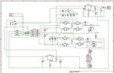
Thank you Arlo1. Is there a link for your project? I am "saving" the links on project page: http://smartebike.sourceforge.net/
 
Here is my powerstage build thread. http://endless-sphere.com/forums/viewtopic.php?f=30&t=35387
Here is the Not simple BLDC controller thread I started. http://endless-sphere.com/forums/viewtopic.php?f=30&t=30851&hilit=not+simple+BLDC
ATM im using lebowskies chip because it seems to have everything I want for programing.
 
Arlo1 said:
Here is my powerstage build thread. http://endless-sphere.com/forums/viewtopic.php?f=30&t=35387
Here is the Not simple BLDC controller thread I started. http://endless-sphere.com/forums/viewtopic.php?f=30&t=30851&hilit=not+simple+BLDC
ATM im using lebowskies chip because it seems to have everything I want for programing.
Lebowskies firmware is closed source. Yours power stage and Not simple BLDC controller are closed source? can you please clarify this (I am just interested to link/use OpenSource tecnhology).
 
casainho said:
Arlo1 said:
Here is my powerstage build thread. http://endless-sphere.com/forums/viewtopic.php?f=30&t=35387
Here is the Not simple BLDC controller thread I started. http://endless-sphere.com/forums/viewtopic.php?f=30&t=30851&hilit=not+simple+BLDC
ATM im using lebowskies chip because it seems to have everything I want for programing.
Lebowskies firmware is closed source. Yours power stage and Not simple BLDC controller are closed source? can you please clarify this (I am just interested to link/use OpenSource tecnhology).
I never registered as "open source" but My not simple bldc, and powerstage threads are open source.
Lebowski's is closed source but for now its fine. There is SO much work to get the rest done its not a big deal.
 
Arlo1 said:
I never registered as "open source" but My not simple bldc, and powerstage threads are open source.
Ok, I expected a statement of intentions :)

I linked here: http://smartebike.sourceforge.net/doku.php/start?&#links_to_other_projects
Thanks.
 
I am very luck to live in a city (Aveiro - Portugal) that have nice guys, like one that own a small shop for selling and repair electric scooters and bicycles, and other that develop OBD-II reader for Android devices (cars On-board diagnostics).

I know Paulo Pires, the developer of OBD-II reader for Android devices and he got interested in helping this project. He offered help to develop an app/lib for the Android and iOS :) -- this are great news!!
 
New site and github

I moved the git code to Sourceforge (from github) and also created a wiki (using DokuWiki) and the site was: http://smartebike.sourceforge.net/
For some reason DokuWiki installation is very slow on SourceForge and so I decided to try others free web hosting and I ended up with http://byethost.com/. I also moved git back to github, since looks like everyone is familiar with that.

The final web address for wiki is (which I like): http://www.smartebike.likesyou.org/
And the git account: https://github.com/casainho/EBike-Smart-Controller
 
I moved to another prototype version (V2) because of this issues: although the motor works, seems that the KU63 circuit for mosfet drivers can't be drived correctly with the 3.3V from the LPC2103.

I also bought a new motor Q85 for rear wheel and a new bicycle, where I will use this motor and the controller prototype for testing.

I also finished the schematic of prototype V2 and also bought the needed components to assembly it. Here is the schematic of prototype V2:
 
Back
Top