Using Fardriver's LIN protocol

Joined
Dec 14, 2022
Messages
16
Hi,

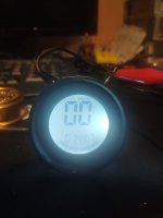
been using Fardriver controller for a couple of years and am familiar with the output of the speed via analog/digital lines. But last week I discovered a display that is also reading the state of the battery and the ride mode (hi, mid, low) from the Fardriver's digital line.

Has anyone any experience with implementing this? I see in the parameters there is 'O BattCoeff' and '100 BattCoeff', which must be used for the SOC% but know nothing more.

We're building our own display and would like to understand the communication protocol and how we might read that.

Thanks,
LG.
 
If the protocol and data format is published by the controller or display manufacturer, you can just use that--but what documents ever get published for these things tends to be incomplete so you might have to make some guesses or experiments. :(

Otherwise you're probably going to have to "sniff" the data passing between them and comparing to what is shown on the display to decode it. (this has been done for some systems around the forum, mostly CANBUS PSUs, but I don't remember one for the FD).
 
Thanks for your quick reply. I sent off requests to Fardriver and the display maker to ask for details. Like you say, it's 50-50 on the usefulness of what will come back. If it's good though, I'll share here. The functionality of displaying FD's info and perhaps via touchscreen switching mode, recuperation on/off etc seem worth the effort.
 
@lord_gammon Were you able to gather any more information on this? I would also like to display data on a screen from a Fardriver controller using either a raspberry pi or ardiuno if I can find information. Thanks
 
This is the full documentation on the protocol used.
It has nothing to do with LIN.
Signal level is TTL but the bits themselves are being sent in a specific maner.
It should be pretty easy to read with an arduino/esp32.
Will do that the following days as I need that data for both my fardriver and my votol.
 

Attachments

  • SFI-One-line.pdf
    53.3 KB · Views: 76
A little update. I played around a bit with the "one wire" display output and was able to decode the data with a simple arduino nano.
Here's some rough test code, nothing fancy, just a simple proof of concept but it works well for me.
Protocol documentation in previous post.


#define sif_pin 2
short battery = 0;
short current = 0;
short currentPercent = 0;
short rpm = 0;
long faultCode = 0;
bool regen = false;
bool brake = false;
unsigned long lastTime;
unsigned long lastDuration = 0;
byte lastCrc = 0;
byte data[12];
int bitIndex = -1;
void setup() {
Serial.begin(115200);
pinMode(sif_pin, INPUT);
lastTime = micros();
attachInterrupt(digitalPinToInterrupt(sif_pin), sifChange, CHANGE);
}
void loop() {
// put your main code here, to run repeatedly:
}
void sifChange() {
int val = digitalRead(sif_pin);
unsigned long duration = micros() - lastTime;
lastTime = micros();
if (val == LOW) {
if (lastDuration > 0) {
bool bitComplete = false;
float ratio = float(lastDuration) / float(duration);
if (round(lastDuration / duration) >= 31) {
bitIndex = 0;
} else if (ratio > 1.5) {
// bit value 0
bitClear(data[bitIndex / 8], 7 - (bitIndex % 8));
bitComplete = true;
} else if (1 / ratio > 1.5) {
// bit value 0
bitSet(data[bitIndex / 8], 7 - (bitIndex % 8));
bitComplete = true;
} else {
Serial.println(String(duration) + "-" + String(lastDuration));
}
if (bitComplete) {
bitIndex++;
if (bitIndex == 96) {
bitIndex = 0;
byte crc = 0;
for (int i = 0; i < 11; i++) {
crc ^= data;
}
if (crc != data[11]) {
Serial.println("CRC FAILURE: " + String(crc) + "-" + String(data[11]));
}
if (crc == data[11] && crc != lastCrc) {
lastCrc = crc;
for (int i = 0; i < 12; i++) {
Serial.print(data, HEX);
Serial.print(" ");
}
Serial.println();
battery = data[9];
battery = data[9];
current = data[6];
currentPercent = data[10];
rpm = ((data[7] << 8) + data[8]) * 1.91;
brake = bitRead(data[4], 5);
regen = bitRead(data[4], 3);

Serial.print("Battery %: " + String(battery));
Serial.print(" Current %: " + String(currentPercent));
Serial.print(" Current A: " + String(current));
Serial.print(" RPM: " + String(rpm));
if (brake) Serial.print(" BRAKE");
if (regen) Serial.print(" REGEN");
Serial.println();
}
}
}
}
}
lastDuration = duration;
}
Thank you for this share.

I am new in e-bikes so I know little about them. I bought something similar to Citycoco M1. Since it's motor driver is way to weak I changed it to Fardriver ND72530. I made my connections and everything is working except Speedometer. My speedometer is at the attachment. My gauges are round and voltage gauge is on left, rest is on right. It looks like a chopper bike so I don't want to change the look of it. I am trying to use this gauge with ND72530. If I can't echieve my goal, my plan is to use the lcd of this gauge and drive it with an Arduino. But another problem here: I searched for the LCD also and could not find which pin is what.

Can this gauge be compatible with Fardriver controller? If not, do you have any suggestions?
 

Attachments

  • WhatsApp Image 2023-12-29 at 00.40.57.jpeg
    WhatsApp Image 2023-12-29 at 00.40.57.jpeg
    92.8 KB · Views: 9
Thank you for this share.

I am new in e-bikes so I know little about them. I bought something similar to Citycoco M1. Since it's motor driver is way to weak I changed it to Fardriver ND72530. I made my connections and everything is working except Speedometer. My speedometer is at the attachment. My gauges are round and voltage gauge is on left, rest is on right. It looks like a chopper bike so I don't want to change the look of it. I am trying to use this gauge with ND72530. If I can't echieve my goal, my plan is to use the lcd of this gauge and drive it with an Arduino. But another problem here: I searched for the LCD also and could not find which pin is what.

Can this gauge be compatible with Fardriver controller? If not, do you have any suggestions?
On my ebike I have a votol and I'm using an incompatible KT LCD8H display. On my motorcycle I'm using a fardriver on the stock display that works via RS485. I needed this so I can make those 2 setups work.
You need to investigate the specific protocol your display uses. I've seen the SIF protococol used by votols and fardrivers reffered to as YXT, One-LIN, One-line, single wire, ISDN, etc... So you need to do your homework. If it's SIF you just plug the communication wire and the ground and the rest might be just settings in the fardriver app. If it's a different protocol , as soon as you can send data to the display, you can use an arduino or esp32 to link them.
 
A little update. I played around a bit with the "one wire" display output and was able to decode the data with a simple arduino nano.
Here's some rough test code, nothing fancy, just a simple proof of concept but it works well for me.
Protocol documentation in previous post.


#define sif_pin 2
short battery = 0;
short current = 0;
short currentPercent = 0;
short rpm = 0;
long faultCode = 0;
bool regen = false;
bool brake = false;
unsigned long lastTime;
unsigned long lastDuration = 0;
byte lastCrc = 0;
byte data[12];
int bitIndex = -1;
void setup() {
Serial.begin(115200);
pinMode(sif_pin, INPUT);
lastTime = micros();
attachInterrupt(digitalPinToInterrupt(sif_pin), sifChange, CHANGE);
}
void loop() {
// put your main code here, to run repeatedly:
}
void sifChange() {
int val = digitalRead(sif_pin);
unsigned long duration = micros() - lastTime;
lastTime = micros();
if (val == LOW) {
if (lastDuration > 0) {
bool bitComplete = false;
float ratio = float(lastDuration) / float(duration);
if (round(lastDuration / duration) >= 31) {
bitIndex = 0;
} else if (ratio > 1.5) {
// bit value 0
bitClear(data[bitIndex / 8], 7 - (bitIndex % 8));
bitComplete = true;
} else if (1 / ratio > 1.5) {
// bit value 0
bitSet(data[bitIndex / 8], 7 - (bitIndex % 8));
bitComplete = true;
} else {
Serial.println(String(duration) + "-" + String(lastDuration));
}
if (bitComplete) {
bitIndex++;
if (bitIndex == 96) {
bitIndex = 0;
byte crc = 0;
for (int i = 0; i < 11; i++) {
crc ^= data;
}
if (crc != data[11]) {
Serial.println("CRC FAILURE: " + String(crc) + "-" + String(data[11]));
}
if (crc == data[11] && crc != lastCrc) {
lastCrc = crc;
for (int i = 0; i < 12; i++) {
Serial.print(data, HEX);
Serial.print(" ");
}
Serial.println();
battery = data[9];
battery = data[9];
current = data[6];
currentPercent = data[10];
rpm = ((data[7] << 8) + data[8]) * 1.91;
brake = bitRead(data[4], 5);
regen = bitRead(data[4], 3);

Serial.print("Battery %: " + String(battery));
Serial.print(" Current %: " + String(currentPercent));
Serial.print(" Current A: " + String(current));
Serial.print(" RPM: " + String(rpm));
if (brake) Serial.print(" BRAKE");
if (regen) Serial.print(" REGEN");
Serial.println();
}
}
}
}
}
lastDuration = duration;
}
Amazing! I've been trying to find a display for my LingBo LBMC 72352 H5C but couldn't find any that fit my chinese electric Vespa clone enclosure, so I did a rough programming with a 3.1" OLED display and ESP32, but instead of using the ONE LINE cable, I went old school with speed being provided by the hall sensor, battery voltage from a battery wire and so on.

I will try to flash your code and see if I can get any output.
it's gonna need some tweaking on esp32 as I found out for myself. Perhaps take a look here:
void sifChange() {
if (!btConnected)
return;
int val = digitalRead(sif_pin);
unsigned long duration = micros() - lastTime;
lastTime = micros();
if (val == LOW) {
if (lastDuration > 0) {
bool bitComplete = false;
if (round(lastDuration / duration) >= 31) {
bitIndex = 0;
} else if (lastDuration > duration) {
// bit value 0
bitClear(data[bitIndex / 8], 7 - (bitIndex % 8));
bitComplete = true;
} else if (lastDuration <= duration) {
// bit value 1
bitSet(data[bitIndex / 8], 7 - (bitIndex % 8));
bitComplete = true;
} else {
//Serial.println(String(duration) + "-" + String(lastDuration));
}
if (bitComplete) {
bitIndex++;
if (bitIndex == 96) {
bitIndex = 0;
byte crc = 0;
for (int i = 0; i < 11; i++) {
crc ^= data;
}
if (crc != data[11]) {
//Serial.println("CRC FAILURE: " + String(crc) + "-" + String(data[11]));
}
if (crc == data[11] && crc != lastCrc) {
lastCrc = crc;
for (int i = 0; i < 12; i++) {
//Serial.print(data, HEX);
//Serial.print(" ");
}
//Serial.println();
battery = data[9];
current = ((char)data[6]) * 10;
currentPercent = data[10];
rpm = ((data[7] << 8) + data[8]) * 1.91;
if (rpm < 0) {
//ignore backwards movement
rpm = 0;
}
brake = bitRead(data[4], 5);
regen = bitRead(data[4], 3);
faultCode = 0;
if (bitRead(data[3], 6)) {
faultCode = 8;
}
if (bitRead(data[3], 5)) {
faultCode = 0x80;
}
if (bitRead(data[3], 4)) {
faultCode = 0x20;
}
/*
Serial.print("Battery %: " + String(battery));
Serial.print(" Current %: " + String(currentPercent));
Serial.print(" Current A: " + String(current));
Serial.print(" RPM: " + String(rpm));
if (brake) Serial.print(" BRAKE");
if (regen) Serial.print(" REGEN");
Serial.println();
*/
}
}
}
}
}
lastDuration = duration;
}
 
Appreciate the update. Do you have a git repo with that code?
 
A little update. I played around a bit with the "one wire" display output and was able to decode the data with a simple arduino nano.
Here's some rough test code, nothing fancy, just a simple proof of concept but it works well for me.
Protocol documentation in previous post.


#define sif_pin 2
short battery = 0;
short current = 0;
short currentPercent = 0;
short rpm = 0;
long faultCode = 0;
bool regen = false;
bool brake = false;
unsigned long lastTime;
unsigned long lastDuration = 0;
byte lastCrc = 0;
byte data[12];
int bitIndex = -1;
void setup() {
Serial.begin(115200);
pinMode(sif_pin, INPUT);
lastTime = micros();
attachInterrupt(digitalPinToInterrupt(sif_pin), sifChange, CHANGE);
}
void loop() {
// put your main code here, to run repeatedly:
}
void sifChange() {
int val = digitalRead(sif_pin);
unsigned long duration = micros() - lastTime;
lastTime = micros();
if (val == LOW) {
if (lastDuration > 0) {
bool bitComplete = false;
float ratio = float(lastDuration) / float(duration);
if (round(lastDuration / duration) >= 31) {
bitIndex = 0;
} else if (ratio > 1.5) {
// bit value 0
bitClear(data[bitIndex / 8], 7 - (bitIndex % 8));
bitComplete = true;
} else if (1 / ratio > 1.5) {
// bit value 0
bitSet(data[bitIndex / 8], 7 - (bitIndex % 8));
bitComplete = true;
} else {
Serial.println(String(duration) + "-" + String(lastDuration));
}
if (bitComplete) {
bitIndex++;
if (bitIndex == 96) {
bitIndex = 0;
byte crc = 0;
for (int i = 0; i < 11; i++) {
crc ^= data;
}
if (crc != data[11]) {
Serial.println("CRC FAILURE: " + String(crc) + "-" + String(data[11]));
}
if (crc == data[11] && crc != lastCrc) {
lastCrc = crc;
for (int i = 0; i < 12; i++) {
Serial.print(data, HEX);
Serial.print(" ");
}
Serial.println();
battery = data[9];
battery = data[9];
current = data[6];
currentPercent = data[10];
rpm = ((data[7] << 8) + data[8]) * 1.91;
brake = bitRead(data[4], 5);
regen = bitRead(data[4], 3);

Serial.print("Battery %: " + String(battery));
Serial.print(" Current %: " + String(currentPercent));
Serial.print(" Current A: " + String(current));
Serial.print(" RPM: " + String(rpm));
if (brake) Serial.print(" BRAKE");
if (regen) Serial.print(" REGEN");
Serial.println();
}
}
}
}
}
lastDuration = duration;
}
does this also work on votol?
 
yep. I have both and use it on both
why does it still error when I compile it?
I changed this part. then it can be compiled. Is this true?
crc ^= data; and
Serial.print(data, HEX);


It turns out that in this endless-sphere, if you just enter or paste the code, changes will occur. Can you share file form?
 
If you use the "Code" button under "More Options", then paste your code into this "box" it will leave it unaltered.

Code:
put your code here
and it will be left unaltered            even with lots of spaces
or.23.3.55......wierd punc:;--0_)*)(*)(&(&uation))

If you just paste stuff into the main text posting box, Xenforo (and most other forum software) will reformat it in various ways whether you want it to or not.
 
Cool thread, some interesting stuff here.

I'm wondering about some practical application.
What I'd like is to improve the 3 speed button basically. The 3 speed button works nicely, but as far as I know you can't associate different throttle response modes, only current and speed.

Right now it's basically like this:
Slow mode: 30% max current and 20% top speed
Middle mode: 50% max current and 50% top speed
Sport mode:100% max current and 100% top speed.

What I'd like is to be able to also select different throttle profiles and associate them with each mode:

Slow mode: 30% max current and 20% top speed, throttle mode ECO, throttleAccCoeff 64
Middle mode: 50% max current and 50% top speed, throttle mode Line, throttleAccCoeff 128
Sport mode:100% max current and 100% top speed, throttle mode Sport, throttleAccCoeff 250

Something like that. With the possibility of adding even more modes if I wanted to, because this way any kind of mode can be coded in the Arduino.
I wonder if this is possible using the communication protocol described above, or if this is just some read only/one way data sending from the controller to the screen ?
 
Back
Top