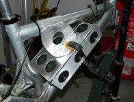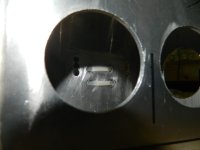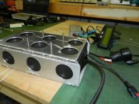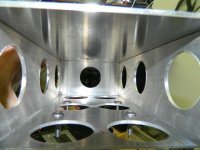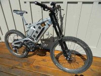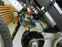
--Wayne's Mac Giant DH to mid drive--

MattyCiii recently reported that he changed the gear ratios on his non-hub drive to get a higher top speed. He is now able to reach 36-MPH, but the motor runs hotter and draws more amps to maintain top RPMs in the higher gear. More heat = more amps = less miles per Ah of battery. Adding a temp sensor will tell you the highest gear you can stay in for max possible speed on a steep uphill. Getting warm? downshift until the heat stabilizes...

Whether aluminum or steel, I am seeing an increasing number of frames with a rectangular battery box welded into the downtube, pic below from Rodgah:

http://endless-sphere.com/forums/viewtopic.php?f=6&t=36682
IMG_0994_zpsc239f574.jpg
 
That is interesting Spinningmagnets, my mac 10 motor that is now in my Giant actually has the sensor in it from when I ordered it from cellman last year.Paul upgraded the phase wires and installed the sensor by the looks of things so when my new V3 CA, battery and compatible controller arrives for the Giant I should be able to have the sensor up and working for me.

Just curious, when I am watching my amp usage on my CA I am assuming that this also will let me see how best to know I am in the right gear for battery consumption. In some ways the amp readout may be more accurate as it is immediate and no lag times for temps to rise and fall?

I have had my eye on the Watt meter for sure and its cool to see it drop even though I am maintaining slope and speed by simple gearing down for climbs with the mid drive. Giant is going to get the mid drive for sure!
 
hey Wayne,

I was playing around with my giant today, I have a ISIS 100mm BB on it, I decided to throw on my Echo freewheeling cranks on to pedal it around, and noticed the freewheel sticks out too far to actually bolt the crank arm on properly. It fouls on the flange of the BB cup (the threaded bit) where it mates with the frame. Since there is very few 100mm BB's and all that I have seen look about the same, I would say that there is no possibility of using freewheeling cranks on this frame. Are you going to set it up the same as you have now with the pedal chain on the left?

Rodger
 
Rodger I am glad you mentioned the BB shell on your Giant. I had not taken the time to measure mine before this. Yikes, mine is wide also. Bummer. To answer your question about the left side freewheel, yes I want to do that again. I like it, crossbreak has a good idea there. What I may try and do is take a hollowtech BB assembly and lengthen the spindle on it.This just comes to mind off the top of my head thinking about it here. Maybe cut the hallowtech spindle in half and weld and insert inside the bore out of the spindle to make it suit the Giants BB width. If there is any way of making the Giant work as close to the set up I have on the hard tail I will try it when I get the time this fall.
 
I think my problems are largely that the massive wide BB is not overall much wider at the spindle, which makes less clearance inboard of the crank arm to the bearing. If you are still running the original raceface cranks you should be able to just switch them sides and call it done as I am pretty sure they are ISIS.
 
Looking at the BB that is on my Giant now I see it is not not going to work for me like the hollowtech set will. The hollowtech style of BB gives the bearing flanges that work so well to fasten the motor mount plates to the BB shell and are so well priced I will pick up the same set as I bought for the hard tail I am thinking. When I get closer to tackling the conversion I will look around to see if there is an off the shelf solution for a Hollowtech style BB that will fit my wide BB Shell.
 
Screen Shot 2013-08-07 at 10.26.42 PM.jpg Battery box is shaping up. Goodies arrived in the mail today so hoping to get the giant back in business soon.
 
box two.jpgView attachment 1box four.jpgbox three.jpgBattery Box is secure now. Zip ties shown in first pic just helps secure things to the down tube for side to side movement. All the weight is anchored from the top tube and bolted onto the bracket with 1/4" x 20 SS machine screws so I can take it all apart if (when) needed. It is a very tight fit, just barley enough room for a little bit of foam on the bottome side of the battery pack and then the overall outer size of the box is also very tight in the front triangle. I had to shave off the tops of the truss head machine screws to make room inside the box for the battery pack. It is sure nice with these forks how the bars are fastened to the fork on either side of center so you have a nice opening at the center of your bars to place the CA right in the middle.
 
Giant new battery.jpg
Back in biz now with the Giant for having a second bike on hand for friends to ride. As luck would have it the same day I got the Giant back on the road the little hard tail has shut down. I will start to trouble shoot things when I get the time but I am pretty sure its something electrical like wires or maybe the controller. Its weird as the conversion project will work just fine like normal but then all of a sudden it will start making a rat a tat kind of low pitched growl or stuter rattle. No power comes out of the motor when it is acting up like this. I shut it down for the overnight and it started working great again then after a short ride 1 kilometer max it started acting up again. I really dont think its anything mechanical but not so comfortable trouble shooting the electrical part of this. I will open up the converted motor on the hall sensor and phase wire side to see if there is something obvious like a loose wire. If its an electrical issue I wont know what to do unless its a loose or burnt wire staring me in the face.

Any tips out there appreciated as to what to start looking at would be great. I realize its hard to diagnose with my rat a tat discription of the noise its making but does this at all sound like it may be a controller issue or maybe hall sensor or phase wire issues?

And to report on the new v3 CA and new pack and placement I will say its a huge improvement. Throttle is dialed in with no dead spots and with the 58volts hot off the charger I am able to hit 28mph on the flats no problem. Weight placement of this one pack is way better than the old placement, this feels and goes better.
 
Nice work on that box Wayner!

Hope you get the hard tail up and running. (so I can borrow it) You know I'm always up for a ride if you need a riding partner. :)
 
I am pretty sure I have sorted out the problem but some further road testing will tell. I noticed that after each time I shut the bike down for a while and come back to the bike for a test ride it works perfect till I climb a few hills back to my place. I set the max amps on my controller through the settings on the V3 CA to be 25 amps instead of 35 amps. We have had some very hot weather here in these parts as well and the combination of the heat and the high amps through this controller may have been the issue. It has done a few miles now with no problems on the 25 amp setting. If it passes the 10 mile test I will ramp up to 30 amps and see how that goes. If this was in fact the controller acting up does anyone know if I have done it any harm with it acting up a few times on me like this. I also noticed the last time it stutered and growled along with no power coming out of the motor I was getting a very low watt reading on my CA even at full throttle during the stutter and growling issues. Keeping my fingers crossed that the lower amp limit will keep things happy, any one with similar symptoms with controller causing this kind of behaviour feel free to chime in please.
 
sounds indeed like a controller problem or maybe a bad solder at your phase wires? I solder to the phases for at least half of an inch. Did you use thick AWG10 phase leads or did you leave them stock?

Your 12Fet controller should have no problem with even 45amps if it has 4110Fets and beefed traces. Your MAC should have no problems with that either if you used proper thermal compound on your heatbridge. I bet on a controller malfunction
 
Screen Shot 2013-08-10 at 3.22.41 PM.jpgThanks crossbreak. The specs on my controller are........
Specification:......from cellmans site............

12pcs of Genuine IRFB3077 Mosfets. Just about the best 75V TO-220 Mosfet available
63V Caps, Max input voltage is limited to 60V
36-50V operation, 60V max
40A Current Limit
4mm2 (>11AWG) High Temperature Silicone wires used on Phase and Supply cables
Dimension: 180 * 85 * 45mm
Weight: 0.54kg
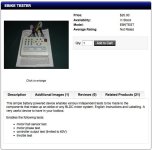
so it looks like I have the 3077 mosfets. I have the tester shown in the attachment here so I will read up on how to use it.

Testing the bike further today even at 25 amp limit I still had the problem show up again however it rode for quite a bit before the growling and no power symptoms showed up with this 25amp limit. My original plan to plug in my Giant controller and leave the bikes side by side with the hartail on the stand will not really work as it happens too sproratically to duplicate it on the stand. I am too lazy right now to switch out the controllers but this is my next option. At this point I will learn more about my Controller tester and how to use it and see where this leads.
 
I talk of the motor phase leads. Maybe this happens only if you ride the bike. You have to swap the controller. These controllers can be bought here around the corner for almost the same price cellman takes, I'm familiar with them. Shouldn't be too much work to swap the controller..just plug and play ;)
 
bomb bike one.jpg

I have ordered a replacement controller even though it may be a phase wire or something inside the motor. I figure it will be good to have a back up controller anyways and it will be compatible with both bikes. I had the brain wave today of using an old eb3 controller that was in my spare parts box but is not set up for the version 3 CA which means I will bypass the V3 CA on my bike and plug in the old controller directly to motor and battery along with an old throttle that is also needed for to be compatible with this old controller. So for testing its all kind of cobbled together with duct tape etc and looking very much like a two wheeled bomb. Its an ugly duckling for sure in this state. Getting dark now so I will wait for the morning for a test ride. It does power up on the work stand and spins up the wheel so I feel I have accomplished some thing for my trouble shooting today. If my test ride goes good tomorrow and things work OK I can just park the bike until the new controller arrives, if it still acts up I will look inside the converted motor. There is a good chance I have messed up some of the phase wire soldering or something like this who knows. If nothing else I feel I have learned a bit about reconfiguring different connector pin outs and soldering up a bunch of old parts to make the best of things.
 
It ran solid for about ten minutes with my spare parts and what not, but then after a short break it started acting up again so I now feel it is not the controller or the CA as I bypassed those and I still got it to reproduce the problem. Looks like its back to the drawing board so I will take apart the stator side of the motor and check out the wiring. I am hoping to see something obvious like a loose wire. I may also forget all the connectors for phase and hall sensor and just solder them together so that is also out the equation. Being a mid drive its not like i need to dissconect the halls or phase wires for wheel or tire changes.

The good news is the Giant is working well with the new battery placement. It eats up the amp hours however compared to the little mid drive.
 
have you tried a sensorless controller? A good tool for trouble shooting ;) Maybe there is someone near you who could borrow one? i would not solder the hall leads to the controller...to much hassle if you want to swap it. Then there is no more "plug and play" :?
 
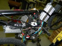
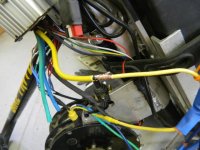
003.jpg006.jpgThanks crossbreak for the tips. Just so I can rule out the connectors I have soldered the phase and hall sensor wires from the motor right to the controller. I can always add the connectors down the road once I get things back to 100% but I can still pull apart the motor for most maintenance needed I think as it is. Photo's show the new wiring arrangement (soldered wires like "amberwolf" recomends) and I feel this is a good start to my trouble shooting. This is turning out to be a bit of a head scratcher for me as the problem only occurs under load and very sporaticaly. I am not wanting to warp my rear brake rotor to place drag and load on the motor for testing. Phase leads looked OK inside the motor but I may have missed something on my inspection the other day.

What has got me really puzzled is after bypassing the phase and hall connectors it worked fine for about one mile and then had a very short an much quieter than before sputter and jack hammer episode. The sound was much softer but none the less it did happen. I powered down and let it sit for a minute and turned the power back on and it has worked perfect for 4 miles of testing. If it was not for this brief hick up I would have thought it was fixed and the problem was the phase connectors for sure. Time will tell and I will keep on with the test miles making sure I don't head down any long hills in case I have to pedal home.

I have had some good tips for trouble shooting phase wires issues but because the problem is so sporatic I have felt its not worth learning how to use my volt meter to do the bench testing. Would others agree with this, that if the problem is very sporatic and only happens under load the volt meter route is not going to help me on the bench?

Who knows maybe it will continue to work fine like it has for the last 4 miles but that one little hick up today after I bypassed the connectors has got me thinking the jackhammer stutter could cause me grief again at any time.

Also this motor has had a ruff life before the conversion. It was run too hot so one of the phase wires lost its solder, I sheared the clutch keystock, and also severed the phase & hall wires at the axle exit when pulling the clutch with a puller. All stupid mistakes by me and I may have damaged halls or who know what when this happened last year.
 
Are you certain its not mechanical? It almost sounds like the clutch might be slipping. This would cause low power draws and no forward movement. and also make a lot of racket when it happens. I would also think it would do it more as it got hotter. Just a thought. I killed a few before I went mid mount!
 
Thanks Whiplash, good thought and I appreciate it but the reason I am thinking it is not the clutch is that during the jack hammer sound and no power output I also at the same time as this is happening I am getting very low and sometime 0 watt reading from the CA with the throttle pinned. So because of this reading on my CA I am leaning toward phase wire connections. Now that I have bypassed the connectors I am wondering if its a phase wire solder at the windings that I did not notice at last inspection when I had the motor apart. I just did 6 mile trouble free except for one little 10 second eposide of no power and light jackhammer noise. I am assuming the hall sensors can be ruled out or is it also possible the hall sensors could cause the weirdness I am experiencing?
 
OK if you got zero waters then it must be wiring. My brother had a phase wire melt once that also did something similar. His was just at the connector though...
 
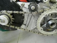
tensioner.jpg
Finally got around to making the chain tensioner shown here. I just used an old jockey pulley (I think that is what you call it) and an assortment of several washers, a few 1/4 x 20 Machine screws and a piece of 1/4" aluminum flat bar and of course the loveable zip tie. I figure I will just tension up the assembly as needed as the chain stretches with the zip tie. Very mickey mouse but it may just work.

Trail riding update........took out a friend last Tuesday with my second bike. It was very cool as we came up over the crest of a hill on a stretch of fire road and we saw a cougar. Very rare to catch a look at these creatures so felt luck to witness this. My riding buddy that day Steve, is also putting together a bike of his own with similar electrics to what I am running on the Giant now.

Motor update....Still working awesome as far as the conversion goes. The issues I am having with it I am guessing are more related to either a phase wire, hall sensor or hall sensor wire as the jack hammer sound still rears its head sporatically. I am not concerned and when I get the time I will take it all apart and install new hall sensors and wires and upgrade the phase wires to all new and thicker. Should be simple enough and because of the issue only happening once in a while I feel instead of trying to diagnose it on the bench ( which also I don't know how to really do) it may make sense to just redo all of the above and be done with it.

Its interesting riding both bikes side by side with my friend. Its for sure cool to have the mid drive for its effeciency and the top speeds etc but if you are not pushing your bike and the terrain you are riding suite the happy zone of a hub in the wheel there is something to be said for the quiet of the hub motor in the wheel. Its so darn quiet. Motor noise aside the chain also is a constant noise maker with the mid drive. Who knows I may keep the Giant as a simple hub in the wheel and use the mid drive for big hill climbs or for enjoying its top speeds on trips on the payment for grocery shopping. I am pretty sure with my street tires and clipless pedals I could do 40mph on the flats with the mid drive. Right now with the dirt tires and flat pedals if I really pedal hard I can hit 38mph. This is slow for most high powered rigs but for 50 volts I am pretty happy.
 
hall sensor .jpgNow that I have my jst connectors in place for hall sensor wires I am able to get some voltage readings on the wires. I was in luck today when I powered up the bike on the stand with my voltmeter in hand as the motor was acting up so this was the ideal chance to see what was going on.

First I tested Black wire to Red wire and it reads 4.39 V so I think this is ok. I have read its supposed to be 5 volts but I am guessing this reading of 4.39 is close enough.
Second I tested between black and yelo wires while slowly spinning the motor backwards and got a voltage change between .03v and 4.89v so this is good if I understand things right.
Third I tested between black and green and it was .03 and 5.06 so this also is good.
Fourth I tested between black and blue and I got a steady reading of 5.06 and no drop in voltage when I spun the wheel slowly in reverse as I did with the other wires. So I am pretty sure it is the blue wire or its hall sensor that is the problem.

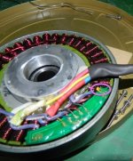
OK...... so feeling like I am narrowing down the search and will pull the stator from the mag bowl this week end and hope to replace the hall sensor and its wire for the blue duties.However I do have a few questions when looking at the inside of my motor as shown in the attachment here.

1....What is the little yelo thing that I have circled in purple that is sitting on or in the green plastic thing that is holding the hall wires and hall legs?
2.....What is this green thing? I saw one photo on line of hall sensors in a different motor and with its wires & it just looked like the legs of the halls were soldered right to the wires going to the controller with no sign of this green thing sitting in the stator area. Is this green piece of plastic kind of like a circuit board? I am assuming so and not sure if I should try to bypass this green thing and just go with a straight connection from the hall legs to the wire and then to the controller?
..........any tips appreciated.........thanks Wayne
 
the green thing is the pcb for the sensors. the yellow thing is a filter cap (i guess).

Ever thought of going for a sensorless controller? Always need one at least for trouble shooting. You would have found this issue within minute if you had one
 
Back
Top