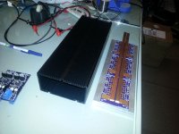
ZombieSS's power stage for Lebowski's controller video pg17

running at 50V is all good, but I can't get it to go over about 30mph at 75v without it faulting. Something is causing an issue. I have the eprm limit set to 200k to eliminate it, tried setting all the error current settings to the same as my battery. played around with the loop a lot but it doesn't seem to make a difference. Always faults in the chip.
 
Ok, I turned FOC on, all problems are gone and it does have more torque. I upped the menu E e/f settings to 80/4 respectively to increase the off the line hit and it's just about perfect. Tomorrow I'll be moving over to my big battery harness which is setup for 24S and has a 250A fuse in it, then it's time to up the power. I was going around 50mph tonight. I can't get the MOSFETs over 40C no matter how hard I try. I didn't get any video of me ripping around on this 7kw setup, but I should be able to do that tomorrow.

This is freaking awesome!

On a more serious note, why did I need to turn on FOC to get the controller to stop faulting at high speed in sensorless mode. no settings changes I made would solve it.

I also have the startup parameters good enough that I have a high torque sensor start transitioning to sensorless mode at 300 eRPM! I also went to 200% sine wave, but I didn't really notice any noise difference, I think it did seem to pick up a little top end power.

No faults, just beautiful high torque silent power with great throttle response. I need to get the 2nd throttle installed and figure out how to program it for regen.

Any tips on the 2nd throttle setup for variable regen would be greatly appreciated.

I had my temperature data logger hooked up. No matter how hard I rode the setup, I was unable to get the MOSFET case temp over 40C, then again it is attached to some very large pieces of aluminum with a lot of surface area.
 
Video of the controller in action. This is on 48V, 200A phase, 100A battery. New videos will be coming soon.

[youtube]0F-ktvyASis[/youtube]
 
What do you mean with you cant get the FETs over 40 A ?

Regarding variable strength regen: it's as simple as hooking up the second throttle and calibrating it in the throttle menu. For regen you want to
make the three throttle curve coefficients negative. Lastly, in the currents menu you must enter a value for allowed regen battery current (this is
the max current you want flowing into your battery under regen conditions, similar to your max battery charge current)

Ah, Ok, just saw the video :D , you mean 40C...

Correct timing of the signals to the motor is very dependent on things like motor speed, throttle current etc etc. Without FOC it doesn't
take everything into account, it effectively makes timing errors which can lead to error currents. FOC however means there's a LOT more stuff
to calculate, it almost doubles the load on the processor. But, it'll still run at more than 40kHz sampling rate, so no biggie...
 
^++ on the vid; really displays how quiet it is even on the slow climb.
In a word: Beautimous 8)

:?:: For 2WD, is that two brains or one w/ two power stages. Just askin... :twisted:

Really impressive, KF
 
2wd, best is to use two brains and connect the throttle either analog or over CAN bus.

With 2 brains the phase and speed of the motors need not be the same, and with different air pressure etc etc 2 wheels will never run in sync...
 
Thanks Dude, good to know 8)

I'll redirect my future Brain questions to your thread.

Nice work guys! KF
 
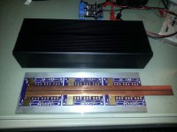
Here is what my new controller is going to look like. I have all the parts but still need to finish the design of the brain board. This should do 300A phase and I think I can safely push it to 333A, 111A per MOSFET since I am matching them. This version should be a lot more fun with my high speed Cromotor in the videos I'm making. With a regular Cromotor the 200A controller should be plenty. I'm going to switch to my 16" rim with a normal Cromotor this weekend and give it a test using the same 100V battery pack and current settings. More videos to come.

new-albis-controller1.jpg

new-albis-controller2.jpg

One thing I have noticed using this controller vs the typical Xie Chang controllers is how much better the throttle control on this one is. The Xie Chang controllers certainly have more initial punch off the line, but that's because they tend to over shoot the current. The EB3 controllers have less punch than the EB2s do since they appear to do a better job at limiting current. If I set my 24 MOSFET Xie Chang controller to 150A battery, 200A phase and use the same battery pack, it will have faster acceleration and more punch off the line than this controller. That's because it's overshooting the current. After feeling the difference I'm guessing it's overshooting the current by quite a large amount. It's no surprise to me that the cheap Chinese controllers can die sudden and sometimes violent deaths when pushed hard now that I feel the difference with real phase current limiting.

Here is some more video of my riding around on this controller with a 100V 18AH battery pack. Settings are 225A phase (I'm pushing the sensors beyond their 200a limit but still just barely in range based on what I saw from my scope when bench testing them), 150A battery current. I need to switch to some higher current sensors if I want to really push the limits of this controller and see just how high it can go with 4 paralleled MOSFETs, but the reality is 200A should be a safe number from what I'm seeing temperature wise. Max speed recorded in this video was 51mph on GPS which is as fast as it will go on a 75V pack. I need more road since I don't have enough current to accelerate me faster.

Good news is I ran the 100V pack for several miles of abuse and didn't have any faults, so initially it looks like my gate driver / power stage design is pretty stable. It needs more testing, but this is very promising, especially since my MOSFET case temps are staying low, 60C was the hottest temp I could get it to directly on the MOSFET tab.

[youtube]2f4Asgt1gjY[/youtube]
 
zombiess said:
Here is what my new controller is going to look like. I have all the parts but still need to finish the design of the brain board. This should do 300A phase and I think I can safely push it to 333A, 111A per MOSFET since I am matching them. This version should be a lot more fun with my high speed Cromotor in the videos I'm making. With a regular Cromotor the 200A controller should be plenty. I'm going to switch to my 16" rim with a normal Cromotor this weekend and give it a test using the same 100V battery pack and current settings. More videos to come.

View attachment 1


One thing I have noticed using this controller vs the typical Xie Chang controllers is how much better the throttle control on this one is. The Xie Chang controllers certainly have more initial punch off the line, but that's because they tend to over shoot the current. The EB3 controllers have less punch than the EB2s do since they appear to do a better job at limiting current. If I set my 24 MOSFET Xie Chang controller to 150A battery, 200A phase and use the same battery pack, it will have faster acceleration and more punch off the line than this controller. That's because it's overshooting the current. After feeling the difference I'm guessing it's overshooting the current by quite a large amount. It's no surprise to me that the cheap Chinese controllers can die sudden and sometimes violent deaths when pushed hard now that I feel the difference with real phase current limiting.

Here is some more video of my riding around on this controller with a 100V 18AH battery pack. Settings are 225A phase (I'm pushing the sensors beyond their 200a limit but still just barely in range based on what I saw from my scope when bench testing them), 150A battery current. I need to switch to some higher current sensors if I want to really push the limits of this controller and see just how high it can go with 4 paralleled MOSFETs, but the reality is 200A should be a safe number from what I'm seeing temperature wise. Max speed recorded in this video was 51mph on GPS which is as fast as it will go on a 75V pack. I need more road since I don't have enough current to accelerate me faster.

Good news is I ran the 100V pack for several miles of abuse and didn't have any faults, so initially it looks like my gate driver / power stage design is pretty stable. It needs more testing, but this is very promising, especially since my MOSFET case temps are staying low, 60C was the hottest temp I could get it to directly on the MOSFET tab.
Whats the bottom of those boards look like?
 
Arlo1 said:
Whats the bottom of those boards look like?

I posted the KiCAD files in a new thread I started a while ago if you want to see them. It's a 4 layer board. Bottom side has all the caps and phase output wires, I'll post some pics when I start building them. The metal plate actually goes on top of the boards, not under it as pictured. I have just enough space to fit the caps with a 0.25" plate 3.5x10" long. Driver boards hang off each board at a 90 degree angle. I just ordered the copper for the bottom of the board today so I'm almost ready to build them up and machine the heat sink plate.
 
I know what you mean regarding the punch at start. AFAIK the china controllers have a parameter called block time where it is set to deliver way more current for a very short time. You can get a similar effect by using for instance 600A current sensors and setting the phase amps to 600, but limiting the battery current to only 50A or so.... but wait, no-one is going to build a 600A controller and then limit its power output by chosing a low battery amp setting...

Have you tried sensorless push-start ? It should be possible to start just from one little push off with your foot, no need to peddle for 2 yards. I've actually been able to start my AF motor in this mode by just blowing at it....

For me it's very nice and satisfying to see someone ride around using my controller IC :D
 
zombiess said:
Arlo1 said:
Whats the bottom of those boards look like?

I posted the KiCAD files in a new thread I started a while ago if you want to see them. It's a 4 layer board. Bottom side has all the caps and phase output wires, I'll post some pics when I start building them. The metal plate actually goes on top of the boards, not under it as pictured. I have just enough space to fit the caps with a 0.25" plate 3.5x10" long. Driver boards hang off each board at a 90 degree angle. I just ordered the copper for the bottom of the board today so I'm almost ready to build them up and machine the heat sink plate.
Why I ask is because the + and - don't look laminated.
 
Lebowski said:
For me it's very nice and satisfying to see someone ride around using my controller IC :D

It took me a while to get started, then it took me almost a year to get to this point. I told you I was going to build a controller, I just didn't do it very fast since I needed to learn how to design a gate driver and a power stage. Now its much easier. It's a heck of an experience to go through. I too feel ratified that I am able to ride around on a controller I designed, built. It's a bonus that this first design works so well.
 
Arlo1 said:
Why I ask is because the + and - don't look laminated.

They are laminated with internal layers under each of those bars. I believe having those bars close to each other horizontally will also act as a lamination after looking at many magnetics field pics and simulations. Closer is better but its a design compromise I have to make this time. If it sucks or fails I'll post about it. After researching it, I think I am going to be OK because I am mostly following the rules. Internal layers are low current but act as a shield against the electric field. Using the right hand rule the current flowing through the buss bars will create a magnetic field, north and south from the sides of the buss bars because current is flowing the long way through the bars. Its all theory, but you and I have both seen horrible designs make big power and this design is much better than a china controller.
 
I got up and running on one of the regular Cromotors tonight. Got it working the best I could in normal sensorless mode, then learned the FOC parameters and took it out for a spin. It rips pretty good with 200 phase amps, but it would feel much better at 300A phase. Now I need to hurry up and start building my 2nd controller so I can experience higher phase current.

I also tested out sensorless push start. It works very well. The motor tends to pulse at idle before I start, not sure how to stop this behavior.

Need to wire up the 2nd throttle so I have variable regen next.

[youtube]ISMXZWT1VBY[/youtube]
 
zombiess said:
I also tested out sensorless push start. It works very well. The motor tends to pulse at idle before I start, not sure how to stop this behavior.

This is probably noise on the throttle. I know I 'suffer' from this in my setup, but I only have 300mV between throttle closed and fully open.

The ADC's on the 30F series from Microchip are not the best I have the feeling. In my setup for instance, if I use the datalogging feature of
the controller IC I can see there is a lot of noise on the throttle signal, and that it is somehow picking up a signal with the same frequency
as the signals to the motor. At speed the noise injected on the throttle signals average out, but at very very low motor speed they don't...

Secondly, the offsets I measure on the current sensors over 3 different controllers are all the same, about -20mV
for channels A and C and +30mV for channel B. If it were true offset you would expect something random, but it's not, it always shows
the same patern and the same (ballpark) offset size....
 
if I use the datalogging feature of the controller IC I can see there is a lot of noise on the throttle signal, and that it is somehow picking up a signal with the same frequency as the signals to the motor.
its the exact same problem with current sensors. any analog signal that leaves the confines of the brainboard PCB will pickup noise.. sometimes a lot of noise that can even be ""common mode" noise since the motor is floating (with respect to the analog signals). at least with the throttle signal you can really filter it down a lot because it is slow moving signal & bandwidth or group delay is not a factor in EV application. the current sensor feedback is totally different in this regard. also, special consideration should be given to what ground reference you send with the analog signal.. like +5V, ground and signal, 3 wires that go to the analog throttle. are you sending brain board +5V & ground? this is like a big attractor to noise, direct to brain board ground. it is one of the reasons why i separate grounds into two groups, "digital ground" and "analog ground". and i treat these grounds differently. on different layers of PCB but tied together at one point.

anyway.. as you go up in power, these little things matter because your margin of error gets tighter and tighter.
 
HighHopes said:
if I use the datalogging feature of the controller IC I can see there is a lot of noise on the throttle signal, and that it is somehow picking up a signal with the same frequency as the signals to the motor.
its the exact same problem with current sensors. any analog signal that leaves the confines of the brainboard PCB will pickup noise.. sometimes a lot of noise that can even be ""common mode" noise since the motor is floating (with respect to the analog signals). at least with the throttle signal you can really filter it down a lot because it is slow moving signal & bandwidth or group delay is not a factor in EV application. the current sensor feedback is totally different in this regard. also, special consideration should be given to what ground reference you send with the analog signal.. like +5V, ground and signal, 3 wires that go to the analog throttle. are you sending brain board +5V & ground? this is like a big attractor to noise, direct to brain board ground. it is one of the reasons why i separate grounds into two groups, "digital ground" and "analog ground". and i treat these grounds differently. on different layers of PCB but tied together at one point.

anyway.. as you go up in power, these little things matter because your margin of error gets tighter and tighter.
What about using ribbon wire wrapped in foil or is there something with a shield?
 
or is there something with a shield
signal cable is available twisted & shielded & insulated... whatever your heart's desire.

sheilded cable is not needed for current sensor cause they near by. maybe for throttle could be useful cause that is farther away, like 1 meter, but my feeling is it will not buy you that much benefit because simple filtering on brain boar (at board edge where throttle signal enters PCB) would be sufficient.
 
That is awesomely smooth and controlled and silent in your video.

People don't realize how much better it is to ride. I want to see Lebowski brains in every motor controller for every bicycle or EV or RC model or whatever. This is next generation motor control.
 
liveforphysics said:
That is awesomely smooth and controlled and silent in your video.

People don't realize how much better it is to ride. I want to see Lebowski brains in every motor controller for every bicycle or EV or RC model or whatever. This is next generation motor control.
It is very good. When I got the YSR running properly it was amazing! People don't realize how all the little features are so very cool like variable regen and smooth torque throttle the transition from sensored to sensorless and the list goes on. Then there is the VERY important things like the phase current sensing and how It all works which makes it 1000s of times better and more reliable then a china controller! I now have 5 sevcons to program and compare to which I don't think will transition to sensorless do they? They are just stuck in sensored or sensorless all the time and this is likely why Zero spends the time with a fancy Sine/cosine setup..... Anyways I will be able to report against one of the best off the shelf's controllers we can get for a reasonable price to a properly build controller running lebowski's brain soon enough. :)
 
For PM motors, sevcons require encoder at all times to function.

This is more advanced than a sevcon or any commercial EV control I've ever seen a plethora of ways.

If it can be made high enough speed, this could conceivably make the most epic RC controllers, all the and scale all the way up the massive hubmotor dump-trucks or giant ship drive etc.

This is the closest thing out there for being the theoritical 'ideal' controller that it would require to make FEMA simulations actually realistic.

It is like the optimization of motor control. All motor controllers that don't run this method of control will be called '1st gen motor control'.

This is the control strategy that electric vehicle motors will be powered in future vehicles.

If you have a motor that has perfect sinus BEMF, than this would offer you no performance advantage over say a sevcon gen4. However, no motor is perfect, and many quite far from it, it is not optimized to drive them with trap or sinus drive. That reduces one entire harmonic EM loss component from your drive, as well as makes any motor output previously impossibly smooth torque. (Unless your motor had nearly perfect sinus BEMF, then you could have had the same level of smoothness).
 
Back
Top