ZombieSS's power stage for Lebowski's controller video pg17

HighHopes said:
if I use the datalogging feature of the controller IC I can see there is a lot of noise on the throttle signal, and that it is somehow picking up a signal with the same frequency as the signals to the motor.
its the exact same problem with current sensors. any analog signal that leaves the confines of the brainboard PCB will pickup noise.. sometimes a lot of noise that can even be ""common mode" noise since the motor is floating (with respect to the analog signals). at least with the throttle signal you can really filter it down a lot because it is slow moving signal & bandwidth or group delay is not a factor in EV application. the current sensor feedback is totally different in this regard. also, special consideration should be given to what ground reference you send with the analog signal.. like +5V, ground and signal, 3 wires that go to the analog throttle. are you sending brain board +5V & ground? this is like a big attractor to noise, direct to brain board ground. it is one of the reasons why i separate grounds into two groups, "digital ground" and "analog ground". and i treat these grounds differently. on different layers of PCB but tied together at one point.

anyway.. as you go up in power, these little things matter because your margin of error gets tighter and tighter.

I'm an analog IC designer (actually working on an ADC right now), so, know exactly what you mean as the stuff you mention is also important on the scale of an IC...

And this is exactly where I found my throttle issue this evening. What happens (and what I suspected) is that, well, the ADC has a complex mux structure in
front of it to guide 9 possible input pins onto one ADC. What I suspected was that large scale signals on 3 channels (the backemf channels) were crosstalking to my
little throttle signal, but not on the PCB but inside the chip. So what I did is, before I measure the throttle I switch the 3 offending inputs from analog pins to
digital pins (as pins can be configured between being analog or digital inputs). This makes that they are removed from the ADC mux input and are replaced with
ground. And hey presto, clean throttle signal !!!! me happy :D

so it means that the mux inside the chip is not perfect but that there is a bit of crosstalk from one channel to the other. When not in use, best to re-define
the unused channels to digital input, so that they dont peep through the mux into the stuff you want to AD convert...

they don't mention this in the datasheet...
 
re-define the unused channels to digital input
yes! and also ground them through a resistor.

same idea with multipack analog components, like a 4 channel comparator, or 2 channel op-amp or whatever. any spare device should be terminated properly (and listed on schematic as a Spare).
 
HighHopes said:
re-define the unused channels to digital input
yes! and also ground them through a resistor.

same idea with multipack analog components, like a 4 channel comparator, or 2 channel op-amp or whatever. any spare device should be terminated properly (and listed on schematic as a Spare).
No, you misunderstand, I use all 9 ADC channels with analog input signals. But when you're measuring 3 channels the other 6 have parasitic feedthrough inside the mux of the ADC. So the
6 that you're not measuring at that moment are best redefined as digital inputs, even though analog signals are connected. I'm not talking about unused floating IC pins.... That's why
the problem was so difficult to find and is so bad from an IC design perspective.

The 30F's ADC is the equivalent of a 7.1 channel audio system with only 30dB channel separation.
 
Futterama said:
Lebowski, does the MUX crosstalk problem have anything to do with the current sensor measurement mismatch?
Current sensor measurement mismatch ? huh ?

Current sensor mismatch must be eliminated (this is done automatically) because with the hf tone you want to measure the difference in motor
inductances, and you don't want these measurements polluted with gain mismatch from other sources.

The mux crosstalk was very noticable in the throttle signal (20 to 30 LSB's randomy square wave superimposed on the actual signal). It must have also
affected all the other measurements, but the chip runs a lot of digital filters that makes it less noticable... I expect all other signals inside the
algorithm to be cleaned up too, but I didn't really look as I was busy for 2 hours yesterday evening and found how to clean up the throttle only at the
end.
 
Lebowski said:
Futterama said:
Lebowski, does the MUX crosstalk problem have anything to do with the current sensor measurement mismatch?
Current sensor measurement mismatch ? huh ?
I remember reading something about when you measure the analog signals from the current sensors, the ADC does not measure the same value for 0A on all 3 channels, there was some mV mismatch between them. Maybe I misunderstood. It was in this thread, something about offset compensation calibration or something.
 
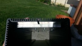
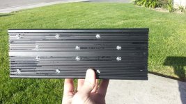
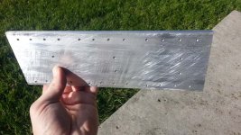
So I finally tried my hand at doing some "machining". I'm not good when it comes to working with metal so this is a bit challenging for me, but I'm learning. 2 days ago I didn't even know how to use a blocking and clamping kit. Today I finished up my heat sink plate, tapped it for 6-32 screws, milled some recesses in the case for screws and then drilled some holes for the screws to pass through. This is far from precision work, but my little mill let me do it better than if I had just done it all free hand. My precision will increase the more I use the machine. I really need to get a digital read out for it since counting turns and working the math for the 16 TPI screws is really annoying. I've had some issues with the indicators sticking on my horizontal axis which makes any kind of precision virtually impossible. It's still better than a regular drill press.

This case is much prettier than the other one, much smaller too. More pics to come as I continue this build.

I'm going to need some shorter screws to prevent them form protruding through the heat sink and possibly shorting to the exposed buss bars. I tried to setup the screw pattern to give me a even clamping force. I thought the middle might need some extra help to go flat against the case so I doubled up on either side of the channel, I goofed on the spacing to make it symmetrical though, oops. At least it's functional.

View attachment 6

View attachment 5

View attachment 4

case04.jpg

case05.jpg

case06.jpg

 
is that aluminium slab supposed to be your heatsink? i hope not.. its in rough shape. i don't know how to do this, but you need a guarteed flatness & polish on it before you mount mostets or you have high probability to create hot spots.
 
HighHopes said:
is that aluminium slab supposed to be your heatsink? i hope not.. its in rough shape. i don't know how to do this, but you need a guarteed flatness & polish on it before you mount mostets or you have high probability to create hot spots.

What you see are the file marks from me deburring it after drilling. I still need to sand it. Those marks look WAY worse than they are, I can barely even feel them with my finger nail. After wet sanding where the MOSFETs will lay they will be a non issue. The interface to the case will be made with an extremely thin coat of thermal paste to fill in any micro gaps.
 
Just got done matching around 70 IRFP4568 MOSFETs I've had laying around for about 2 years. I cherry picked 6 groups of 3 for my controller. I'm happy that I finally get to use them for something other than decoration.

Of interest is how this part had a very wide spread on the matching, similar to the IRFB4115 MOSFETs. I needed to use 2 matching voltages, 4.100V and 4.000V for the 10 outliers that 4.100V produced too low of a D-S resistance to be considered usable.

I'm reiterating myself when I say this, but paralleling a MOSFET from the extreme ends of the spectrum would probably not yield good current sharing. This is something I need to research further, but they certainly will not turn on evenly. If you aren't pushing them hard and are switching fast, this is probably not a big issue, but I tend to push things hard.
 
zombiess, nice work with the machining, it's looking really good.

I hate to ask this, since it's probably somewhere on the forum but I haven't been able to find a "clean" answer. How are your MOSFETs matched? I mean, what exactly do you do, to match them?
 
I measure the drain to source resistance with regard to gate to source voltage. For IRFB4115 and IRFP4568 devices this is usually 3.9-4.2v Vgs to get a reading in the 1k-300k range. I've compared this method to measuring the current draw while in transconductance and seen that the relationship is the same. It's much faster since there is virtually no heating in the MOSFET.

When matching you can not handle the MOSFET with your hands as the heat transfer will alter the reading by quite a bit. Room temperature needs to stay the same and you should have the Vgs voltage regulated to +/- 0.003V to get consistent results. As the temperature goes up the D-S resistance drops, just as Vgs goes up resistance drops. The temperature relationship is an interesting phenomenon, I did not expect a MOSFET to act as an NTC thermistor.

I initially started matching around 2.5 years ago with an LM317 regulator and a multi meter.
 
So basically, you apply a stable voltage to the gate with respect to source, and measure resistance between source and drain?
I guess the multimeter must be connected the correct way to source and drain, otherwise the MOSFET body diode will probably conduct?
 
Lewbowski, do you think the crosstalk is related to ADC manufacturer process?

here's a somewhat related technical question.. seems like it should be something i know but it is not. i have 3.3V DSP and resolver is 5V, so to make the translation i have a lot of options but i use level shifter which is tailor made for this purpose, done. now let's say i have 5V analog sensor, maybe bike throttle for example, how do i make the translation to 3.3V ADC? i thought about this for a long time and the best i could come up with is to use a voltage divider up front (and then standard op-amp signal conditioning circuit), but i was not happy with that answer so i changed all my sensors to 3.3V compatible instead. my thinking was that i would prefer all sense feedback to be 5V for increased dynamic range but my DSP is 3.3V so eventually i have to make a translation. what are your thoughts?
 
That is a good question HH. I myself have never worked with 3.3V parts, but when it comes to ADCs and noisy environments I start to wonder how well they could work with something such as a current sensor.
 
5V to 3.3V translation for analog signals.

1) If you have a 5V rail, buffer it, then resistively divide it. This option has a high Z input impedance, and likely an acceptable output impedance to an ADC. If you need a lower output impedance, add a 3.3V buffer.

2) If only have 3.3V rail, resistively divide it, then buffer it. This option inserts more phase delay and a lower input impedance to the signal source, but has a low output impedance.
 
HighHopes said:
Lewbowski, do you think the crosstalk is related to ADC manufacturer process?

here's a somewhat related technical question.. seems like it should be something i know but it is not. i have 3.3V DSP and resolver is 5V, so to make the translation i have a lot of options but i use level shifter which is tailor made for this purpose, done. now let's say i have 5V analog sensor, maybe bike throttle for example, how do i make the translation to 3.3V ADC? i thought about this for a long time and the best i could come up with is to use a voltage divider up front (and then standard op-amp signal conditioning circuit), but i was not happy with that answer so i changed all my sensors to 3.3V compatible instead. my thinking was that i would prefer all sense feedback to be 5V for increased dynamic range but my DSP is 3.3V so eventually i have to make a translation. what are your thoughts?

Typically with a something like a throttle you have an R-C filter on the board. A 5V throttle to a 3.3V ADC, I would make a voltage divider out of the resistors (wikipedia: look for Thevenin equivalent). I try not to use opamp signal conditioning circuitry, I prefer a simple RC against aliasing and then digital filtering. When you divide down a signal from 5V to 3.3V domain the DR (dynamic range) stays the same as both signal and noise divide down. The resistors used will add some noise though, but with an RC you limit bandwidth reducing noise.
 
Some more video of me testing out the acceleration on a mostly discharged 100v battery. Still gets up and goes pretty good but it's not as punchy and pulling the front end like it had been about an hour earlier.

[youtube]mPhY6-vZbiA[/youtube]
 
Hall sensor mode until 150 erpm, which isn't very far on the ramp. Push start works, but I'd prefer to get the hall sensors to act as my push off.

Gotta try out the new 2.10 chip and see how it does completely sensorless. Sounds like it's less finicky with the tuning than this version. If I didn't apply the throttle just right on the uphill start it would fault to drive mode 0, but it wasn't hard very hard to start off, just not effortless yet. At least I have the tuning somewhat close, haven't adjusted it in a week when I posted the last video with the regular Cromotor.

Here are my settings used in the last 2 Cromotor videos

Code:
########################################
#   (c)opyright 2013, B.M. Putter      #
#   Adliswil, Switzerland              #
#   bmp72@hotmail.com                  #
#                                      #
#  version 1.21                        #
#  experimental, use at your own risk  #
########################################


a] calibrate hall sensors
b] determine coil positions
c) PWM parameters
d) current settings
e) control loop parameters
f) throttle setup
g) running modes
h) CAN bus setup
i) Field Oriented Control
z) store parameters in EEPROM for motor use

------> a

a] number of e-rotations: 92
b] calibrate hall positions
c] table out hall signals
z] return to main menu


------> b

a] number of back-emf samples: 1200
b] calibrate coil positions
c] use only fundamental sine waves
d] reconstruct waveforms based on extracted parameters
e] table out data arrays
z] return to main menu


------> c

a) PWM frequency: 15kHz
b) deadtime: 533ns
c) dutycycle testsignal: 50%
d) toggle high side polarity, now active HIGH
e) toggle low side polarity, now active HIGH
f) test PWM signals
z) return to main menu


------> d

a) number of current sensors: 3
b) current sensor transimpedance: 10.00 mV/A
c) maximum motor phase current: 219.9 A
d) maximum battery current, motor use: 174.9 A
e) maximum battery current, regen: 0.0 A
f) maximum shutdown error current, fixed: 19.9 A
g) maximum shutdown error current, proportional: 19.9 A
h) IIR filter coefficient, throttle current: 2
i) IIR filter coefficient, error current: 5
j) use additional comb filter: NO
k) use offset calibration: NO
l) restore default calibration
z) return to main menu


------> e

a) loop sample frequency: 28.51 kHz
b) proportional phase loop coefficient: 350
c) 1st order phase loop integrator coefficient: 23.0000
d) 2nd order phase loop integrator coefficient: 0.0099
e) proportionale amplitude loop coefficient: 75
f) 1st order amplitude loop integrator coefficient: 2.0000
g) maximum amplitude: 111 %
z) return to main menu

------> f

a) calibrate throttle 1
b) calibrate throttle 2
c) polynomial coefficients throttle 1 (x, x^2, x^3): 0.0998, 0.3798, 0.5197
d) polynomial coefficients throttle 2 (x, x^2, x^3): -0.0002, -0.0002, -0.0002
e) use analog throttle 1: YES
f) use analog throttle 2: NO
   receive throttle over CAN: NO
g) TX throttle over CAN: NO
h) test throttle
z) return to main menu


------> g

a) sensored or sensorless: SENSORED
b} sensorless startup: PUSH START
c} e-rpm limit sensorless self start: 574 erpm
d} minimum current push start: 0.9 A
e} push start current, error allowed: 65 %
f] erpm sensored to sensorless transition: 150
g] transition time sensored to sensorless: 149 milli-sec
h) return to motor start below 400 erpm
i) controlled slowdown for direction change: NO
j) phase current for controlled slowdown: 0.0 A
k) motor maximum, forward: 199.98 k-erpm
l) motor maximum, reverse: 3.99 k-erpm
m) motor standstill voltage threshold: 0.79 V
n) enable low side pulsing in drive 0: NO
o) low side pulsing rate: 52 Hz
p) low side pulsing width: 20 usec
z) return to main menu


------> h

a) CAN 'address': 1
b) CAN CFG1 as per Microchip 30F manual: 0
c) CAN CFG2 as per Microchip 30F manual: 0
   RS232 output rate: 3564 Hz
z) return to main menu


------> i

a) use Field Oriented Control: YES

 Before automatic measurement of the motor parameters
 the controller must be supplied with the same voltage
 as in the vehicle. PWM frequency and deadtime must be
 initialised. ADC's must be properly set up and calibrated
 or calibration must have been restored to default.
 The following parameters must be set at their final value:

 loop sample frequency: 28.51 kHz
 current sensor transimpedance: 10.00 mV/A

b) amplitude measurement current: 49.9 A
c) impedance measurement frequency: 29.99 k-erpm
d) determine motor impedance

e) battery voltage (for impedance display only): 95 V
   measured inductance (star configuration): 133.6 uH
   total system 'resistance' (star configuration): 93.3 mOhm

z) return to main menu
 
Ah, there's one definite mistake in the setup

In menu G you set 150erpm for going from sensored to sensorless, and 400 erpm from going from sensorless to sensored (option f and h)

You're supposed to build in some hysteresis here..

Let's say you're at 300 erpm. It's above 150, so it will go from sensored to sensorless. But then, hey, it's below 400 so it goes from sensorless back to sensored. And it will keep switching between the modes. What you're supposed to do is put in some hysteris. If you swap out the numbers, you go from sensored to sensorless at 400, and back to sensored when it drops below 150. Which means that when it goes from sensored to sensorless at 400, erpm's are solidly above 150 and the controller will not toggle between modes.

Second thing I typically have different, I have each of the error current values about 1/8th of the phase current (so about 30A in your case, much more than the 20 you have) and I use an error current filtering of 7. Lastly, the 0.01 for the 2nd order phase loop coefficient is too low, I would go 0.07 minimum but 0.4 would be best. Probably the very very low value here helps fix your mode transition problem, but if you set the erpm limits correcly the low value here is probably no longer necessary.
 
It needs more testing, but this is very promising, especially since my MOSFET case temps are staying low, 60C was the hottest temp I could get it to directly on the MOSFET tab.

most manufacturers will start to derate their mosfet when the case temperature reaches 60C to 75C. this means that they believe that with a case temp of 60deg you can get full value, but if you allow the case temp to go up then life will be taken off the device. so if you brought your bike up to rated speed and then added load until case temp was 60degC for 30minutes, then whatever that phase current is, that is your inverter's nominal rating. burst rating is something else.
 
I've never given much thought to life span vs operating temperature much, only derating the power as temp went up. I think it was Bigmoose who told me a long time ago that the maximum MOSFET case temp one should run is 80C if you want it to be reliable. I've considered 100C to be my shutdown point during testing, based on the enclosure and cooling I've watched the devices go into thermal run away and the temp climb fast (no this controller, the cheap Chinese ones).

It would be nice if I had a load testing setup that allowed me to run this controller without and then with forced air cooling to see what it's nominal rating might be. Steady state operation at this power level seems like it would be tricky to manage.
 
Nice video! Does it feel as smooth and silent as the video makes it look?

I'm so stoaked to be running one of these on my roadbike. :) If you guys make something big enough, I will swap the Sevcon off deathbike and replace it with the beautiful sensorless future of motor control. :)
 
If you guys make something big enough
funny you should say that.... 8)
 
Back
Top